- Project's Blog: https://hackaday.io/project/196438
- Repository: https://github.com/an-dr/rEmotion
- Parts: https://www.printables.com/model/1004766
Here is everything that we need from electronics
We have to make a special wire joining together four 2-wire connectors. You need to join together two female and two male black DuPont wires + do the same for red wires. I’ve bought a set of different DuPont connectors, so mine wire looks like this
Then, you have to solder your headers to the modules, including the potentiometer. For the potentiometer, you have to solder two headers from both sides so we can connect a pair of wires per contact.
Now let’s print all 5 parts. Download them from Printable:
https://www.printables.com/model/1004766-remotion-robotic-platform
Additionally, you'll need a handful of fasteners
- Bolts M3x6 - x15
- Bolts M3x12 - x 2
- Bolts M2.5x8 - x 4 (optional)
- Bolts M6x30 - x 2
- Nuts M3 - x 4
- Nuts M6 - x 2
Press in 4 M3 nuts into the small parts. You might need players for this
Put 2 big nuts into the main body inserts
Let's mount the display (use x4 M3x6 bolts). Mind the position
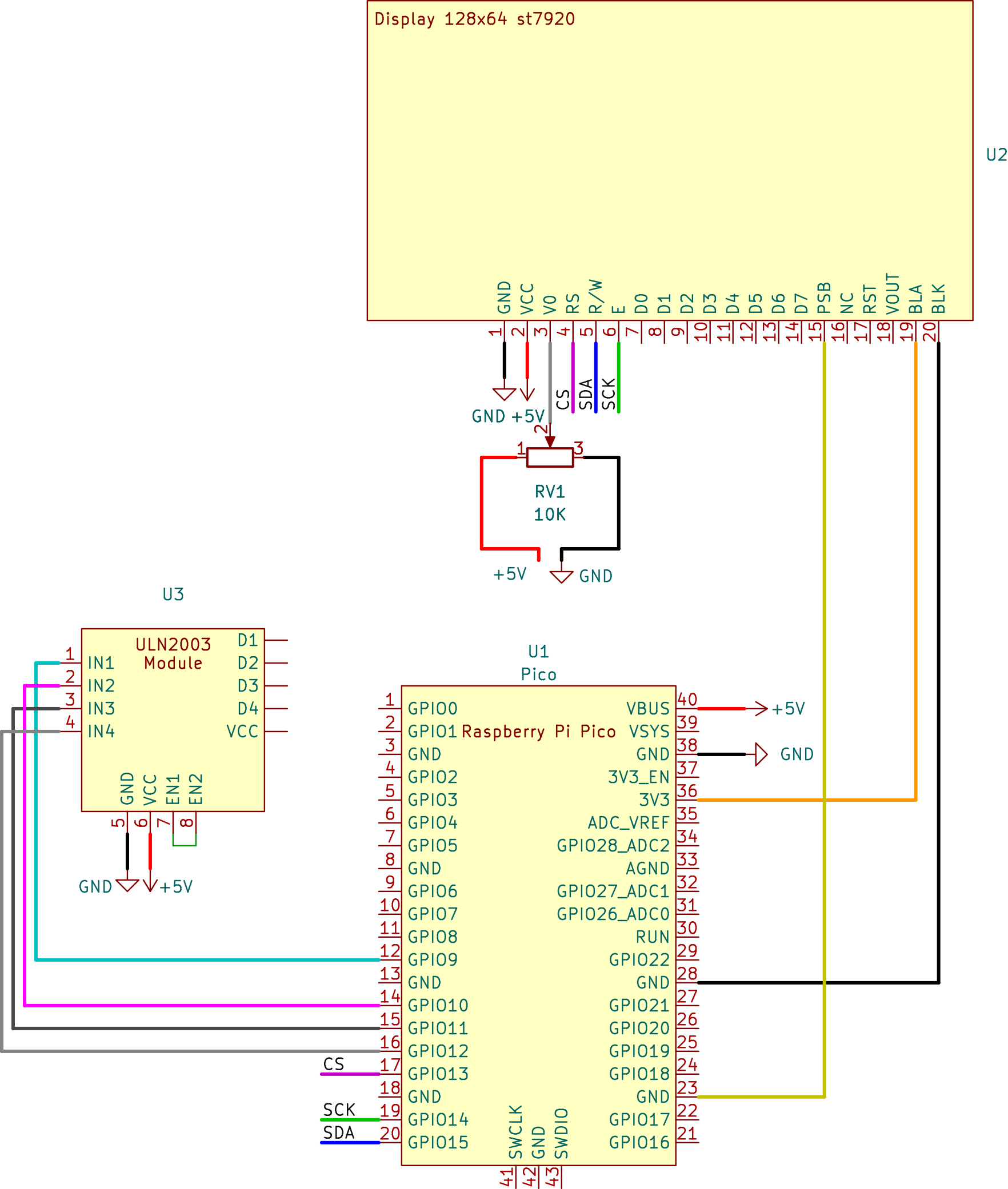
Connect the wires to the display now, as it will make the rest of the assembly simpler (check the schematic)
Assemble the left board (use x3 M3x6 bolts)
Assemble the right board. I didn’t have such small fasteners (M2.5x8), so I just used packaging wires
Attach wires to the left board according to the connection guide and mount it in the body (use x2 M3x6 bolts)
Install the right part (use x2 M3x6 bolts)
Next, connect everything according to the picture and the table below
Almost done!
Attach the USB cable for interfacing with the MCU and put it through a bottom hole
Now put the lid on top and fix it with two M3x12 bolts
Done! Congratulations on your own rEmotion
Further, we will proceed with the assembly of two extension modules - camera and motor
Extension Module - Motor (28BYJ-48)Print the mount and mount the adapter using an M6 bolt. Pass the cables through a rectangular hole
Let’s attach the motor mount to the adapter using four M3x6 bolts
Let’s print the motor base and assemble it.
Then let’s connect the motor wire to the rEmotion’s core
Now attach the base to the mount
And that’s it, we can put the lid back!
For the module, we will use a Logitech C310 webcam, but you can also use C505, Brio 100/105 or C270 (do not recommend the last one).
Remove the plastic cover
Unscrew the lid
Unscrew the PCB
Remove the metal bracket and free the cable
Optionally you can do as I did - replace part of the cable with a connector
Now let’s print the housing
Insert the PCB into the housing and pass the USB cable through the rEmotion’s body
Mount the module using an M6 bolt
Done!
Depending on your project, you may want to expose power and communication pins. Pico conveniently combines UART and I2C on GPIO0/GPIO1
Thank you and happy development!


Comments
Please log in or sign up to comment.