A guide for building a distributed lighting system controlled by natural tilt. Also a perfect project for adding some flavor to your dwelling.
MotivationThis project was inspired by a friend who decked out his apartment with some LED light strips. I wanted to take this to the next step and not only make the lights distributed but also controlled by the flick of a wrist.
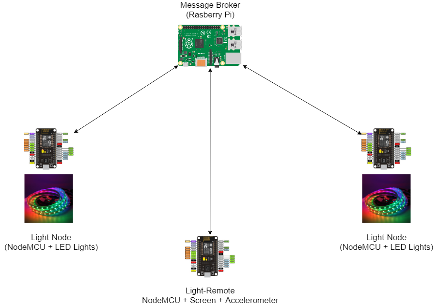
ArchitectureThis guide will walk you through configuring three key components of this system:
- MQTT Broker (Raspberry Pi)
- Light-Remote (Node MCU + OLED Screen + Accelerometer)
- Light-Node (NodeMCU + LED Light Strip)
Refer to the architecture diagram above. We rely on MQTT (Message Queue Telemetry Transfer) as the main communication protocol among our NodeMCU devices. As you can see from the diagram, the Light-Remote is responsible for reading the X, Y, Z tilt values of the accelerometer, converts them to RGB values, and then publishes to the MQTT Broker. Meanwhile, each of the Light-Nodes subscribe to the same topic on the MQTT Broker, read the value sent by the Light-Remote, and display the color on the LED light strip.
Configuring MQTT BrokerConfiguration for this step is only on the Raspberry Pi.
If you have not done so already, set up your Raspberry Pi. Click here for configuring your Raspberry Pi.
Once that is complete, you will need to download and set up the MQTT software called Mosquitto on the Raspberry Pi. Here is a good guide on this. I would play with the command line with this for a bit to get comfortable.
Remember the IP Address of the Raspberry Pi. This will come in handy whenaddressing TODOs from the code when setting up the Light-Remote and Light-Nodes.
Pro tip: Later in the development process, I recommend using Mosquittos's command line interface for sending/receiving MQTT messages to/from NodeMCU devices. If anything needs debugged from the MQTT layer, this will help. You can download the Mosquitto client on your personal computer and publish/subscribe to topics, just like the NodeMCU's.
From my terminal on my personal computer I published to the topic that the Light-Node subscribed to. Doing this verified that the Light-Node was properly consuming from the message queue.
mosquitto_pub -h 192.168.0.106 -t color-remote -m "12,34,56"
Likewise, from my terminal I subscribed to the topic that the Light-Remote published to in order to verify that it was sending accurate inputs. This is a good sanity check to make sure that NodeMCUs receive expected messages.
mosquitto_sub -h 192.168.0.106 -t color-remote
Congrats, you’re now immersed in an MQTT-speaking ecosystem.
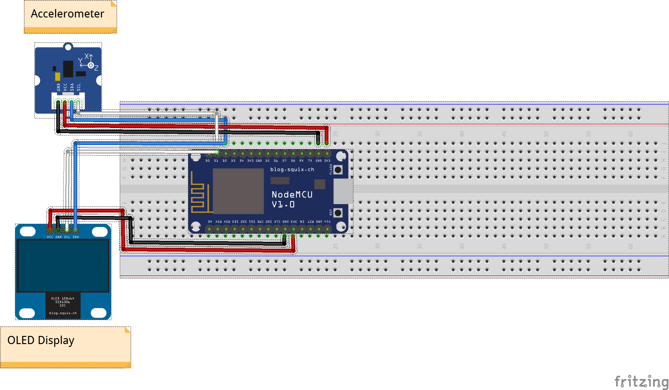
Building the Light-RemoteI encourage you to look at the Light-Remote Hardware Connections Attachments. For the.fzz files, you can look at it through a program called Fritzing. Otherwise, the.png file (directly below) will be sufficient.
I would recommend starting by soldering pins onto the accelerometer. I included some before/after pictures of me soldering it.
I highly recommended completing the next two steps even though they are not totally necessary:
1. Once soldering is complete, follow the schematics and connect the accelerometer to the board. Note that we are using I2C (Inter Integrated Circuit), not SPI (Serial Peripheral Interface) for hardware connections. Then, to make sure that the board can identify that the accelerometer exists, flash and run an I2C Scanner Sketch. This will help you verify that the Light-Remote properly communicates and addresses the accelerometer. If this is done correctly, open your serial monitor and a hexidecimal address will appear. If not, check your wiring and make sure that your connections are good, then run this sketch again.
2. Next, copy this sketch (you should run it in a.cpp file), flash it, and run it on the Light-Remote NodeMCU. This sketch is a demo that takes raw data from your accelerometer and you can make sure that it works as expected. With every tilt, check the X, Y, Z values and verify that they make sense.
Congrats, attaching the accelerometer is complete.
Now, we are going to attach the OLED display to the the Light-Remote. This is not necessary to the functionality of the Light-Remote but I liked knowing the tilt values and getting a read of the RGB values. Just like the accelerometer, follow the attached schematics (at the bottom of this guide) and connect the OLED display to the NodeMCU. Like the diagram shows, the SCK and SDA share the same D3 and D4 as the accelerometer. You can optionally run I2C Scanner Sketch (same as above) to verify that there are two addressed printed in the Serial Monitor. Once this is complete, the Light-Remote should look like this:
Now flash the code for the Light-Remote. Follow the TODOs in the code, such as adding an SSID and password for your network. You can find the code here.
Note how when you click the FLASH button on the NodeMCU, it stops sending requests to the MQTT Broker and freezes the display so that you can read the RGB values that correlate to the lights in their current state. In addition, if you hold down the FLASH button for a little longer and release, it will turn off the lights. To turn the lights back on, quickly click the FLASH button.
Good work, we are finished building the Light-Node. This is what mine looks like:
Follow these same steps for all the Light-Nodes you wish to initialize.
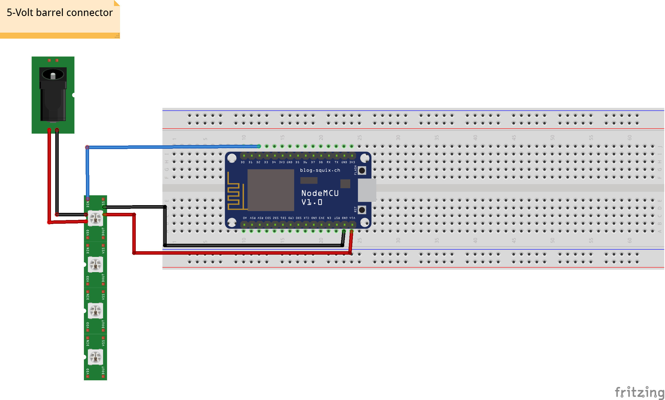
First we need to connect the lights correctly to the NodeMCU. Follow my schematics for the connections to the NodeMCU. However, my fritzing diagram lacks detail on connections to the light strip...
...so if you are having difficulty, I included a video guide to help.
*A particularly important takeaway from this video is that the NodeMCU works with 3.3V and 5V logic. We can leverage the 5V VIN on the NodeMCU without any extra hardware to interface with the5V lights.
Use the barrel jack (included with the 5V power strip) and connect that to the LED light strips' PWR and GND. Use a screwdriver on the barrel jack to tighten the connections. This connection will also power the NodeMCU. See the picture below of the completed Light-Node.
Once you having everything connected, read the code here and address the TODOs. Note that all Light-Nodes need to have different clientIDs, otherwise they will not consume from the MQTT Broker correctly. Once all looks good, flash your Light-Nodes with the code.
Install the Light-Nodes wherever you see fit. Since the lights are bright, I hid my lights under the kitchen bar and behind the couch.
A neat feature of the message broker is that the the Light-Remote doesn't need to know about how many Light-Nodes are in the system. This scales really well with many Light-Nodes and you can add as many as you desire.
I had fun working on this project and learned a lot about NodeMCU, hardware, and how to take a rather involved personal project from start to finish.
I added some additional ways you could build onto this project in case you wanted to take this to the next step.
Feel free to reach out with questions and happy hacking!
Additional Ideas/Directions- Add an extra layer of security and add authentication for MQTT
- Add a sleep mode on the Light-Remote so when not touched for a given time, it goes into a low-power mode
- Making the Light-Remote into a glove and making a 'party-glove' that a host could wear and change the lights effortlessly
- Create an Integration with IFTTT that changes the color of the lights
- Using light strips that are 12V, rather than 5V. From my quick research, the hardware is more complicated, but cheaper


Comments