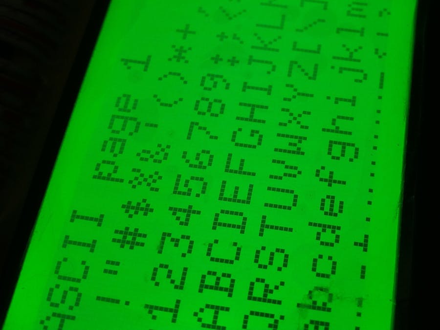
These LCD displays once were popular and sometimes you may pick one up for a couple of bucks or extract it from some outdated peace of hardware. The typical drawback is the lack of documentation, but if it uses some standard controller there should be a way to drive it with Arduino. I was lucky enough because my display was based on a pretty much common ST7565 controller. The model name was VTM88870B V4.0, which gave not much relevant search results. Mostly Chinese. It took some time to collect necessary information, so I share my results to save your time. And your money. Because You'll get an Arduino-compatible graphical LCD display for a low price and with minimal soldering skills.
However you do it at your own risk, and you are responsible for any harm or damage (or experience :)) that you suffer as a result.
This display features both parallel and serial interfaces. To activate SPI mode, you should solder corresponding jumper as it shown on the following pictures.
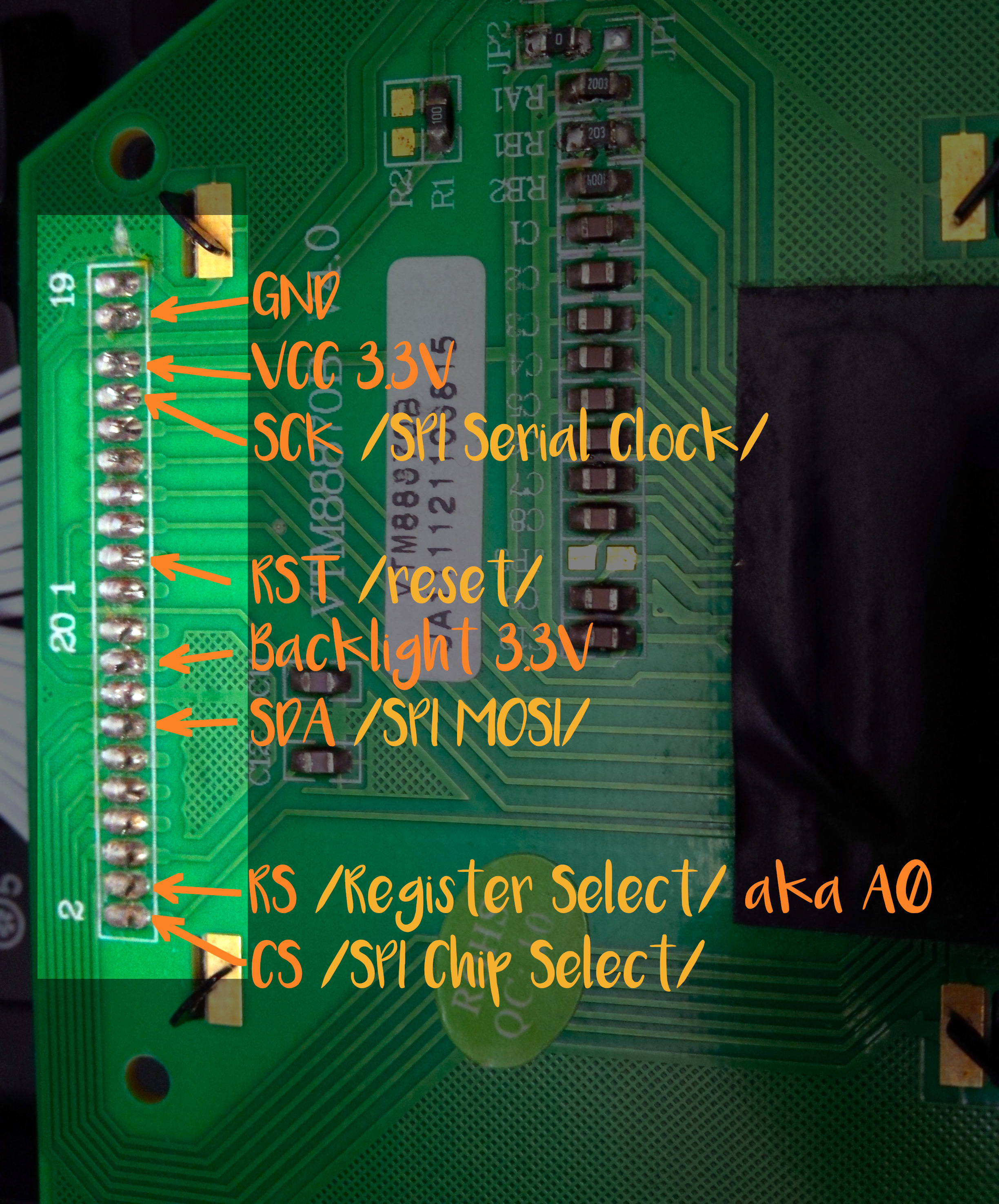
The outputs on the LCD board are numbered but not labelled. I figured out which pins are related to SPI interface and depicted them in Schematics section.
Note that you'll need 3.3V Arduino board to drive this display!
This is how your wiring may look like:
- VCC — Arduino 3.3V
- GND — Arduino GND
- Backlight — Arduino 3.3V
- CS — Arduino D10
- RS — Arduino D9
- SDA — Arduino D11
- RST — Arduino D8
- SCK — Arduino D13
I used u8g2 library since it supports ST7565 controller. If you open any example from u8g2, you'll see a lot of commented display initializing lines. Since my particular display model is not listed there, I tried all ST7565 displays. If you see mirrored or displaced images, keep on trying. The following initializing line worked for me:
U8G2_ST7565_LM6059_1_4W_HW_SPI u8g2(U8G2_R0, /* cs=*/ 10, /* dc=*/ 9, /* reset=*/ 8); // Adafruit ST7565 GLCDNow you should be able to use your display normally.
If your display has different pinout, share it in your comment. It might be helpful for someone.


_3u05Tpwasz.png?auto=compress%2Cformat&w=40&h=40&fit=fillmax&bg=fff&dpr=2)
Comments
Please log in or sign up to comment.