Music projects are fun. This project aims to create a simple and fun noise maker. We will make a five button piano. This piano will play any notes the user presses, but also indicate what is the next note to play. The user will be shown how many consecutive notes have been played correctly. The synthesizer engine used in this project can play up to 4 notes simultaneously.
The heart of this piano is a push button circuit using a switch, an LED (light emitting diode) and a couple of resistors. This simple push button circuit allows the Arduino to both read the status of the push button as well as illuminate the LED under software control. As a side effect, when the button is pushed, the LED is illuminated automatically and it will turn off when the button is released.
The hardware part of this project is relatively simple and consists of 4 parts:
1) Passive Buzzer
2) Illuminated Key Circuit (repeated five times)
3) A potentiometer (to act as a tuning pot)
4) LCD Display
The last two components are optional. This project will work as a piano with just the buzzer and the buttons.
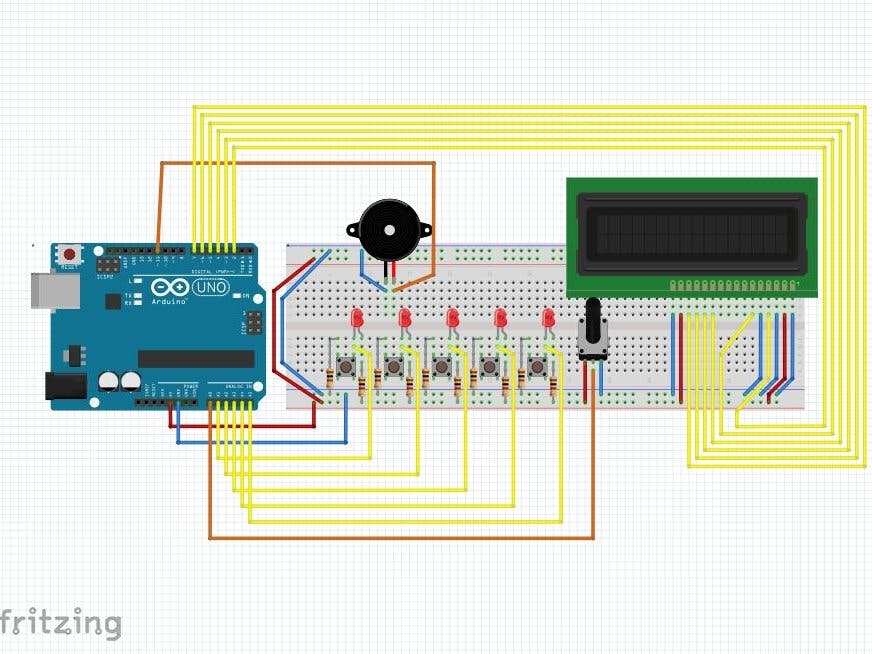
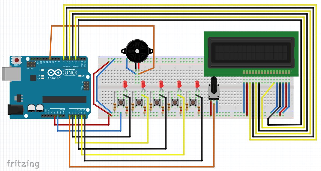
A complete wiring diagram is shown below, further below we will show in detail what each section does.
Sound will be generated through a passive buzzer. The connections are simple, but polarity is important. The negative end of the buzzer connects to the ground bus (blue line) and the positive end connects to the pin that's used by the synthesizer engine to produce sound. Different engines use different pins. The synth we use (DZLOnline TheSynth) outputs sound through pin 11.
If another library, like Mozzi is used, audio will come out of another pin, like 9. To avoid having to switch the output pin that's connected to the buzzer, a simple circuit like the one shown below can be permanently wired. Only one pin, either 11 or 9 will be connected to the buzzer through a 100 ohm resistor. The other pin will be configured as an input and have no effect in the sound.
The main part of this project is the illuminated key circuit shown below. A 1K resistor is connected from the 5V bus (red line) to the LED anode (positive side). The cathode, or other side of the LED, is connected to a wire that goes back to an Arduino pin. If the Arduino drives this pin low, the LED will illuminate. The LED cathode is also connected to one side of a push button. This right side of the push button is normally isolated from the left side. Both sides will be shorted together when the button is pushed. In that case, the LED cathode will be connected to the ground bus through a 100 ohm resistor. This resistor is there to prevent a damage to the Arduino because of a 5V short to ground in case the sense pin is being driven high.
If the button is not pushed, the Arduino will read logic high (1). When the button is pushed, the sense pin will read as logic low (0).
This circuit lets us do fun things like indicate to the user what is the next note to play and detect when the user presses the button.
If this circuit is made into a PCB, the pushbutton and the LED can be arranged to be under a single 3D printed key that will illuminate.
The remaining components are optional. Shown below is a potentiometer that can be used to tune the piano. The connections are simple, the left pin is connected to the 5V bus (red line) and the right pin is connected to the ground bus (blue line). The center pin will pick up a voltage between 5V and 0V. When the potentiometer stem is rotated all the way to the left, it will pick up the voltage of the left pin. When rotated all the way to the right, it will pick up the voltage of the right pin. Thus, it will read 5V when turned to the left and 0V when turned to the right and intermediate voltages in between. If a different polarity is desired, just connect the left side to ground and the right side to 5V.
The middle pin in the potentiometer must be connected to an analog pin and read using the analogRead() function.
The LCD display connections are shown below. It shows which pins must be conencted to ground (blue color) and which ones to 5V (red color). The contrast circuit was eliminated and connected to ground in order to use the potentiometer to tune the piano. The remaining signals (alternating in yellow and black were brought in sequential order to the Arduino pins 2, 3, 4, 5, 6, 7. The built in library was used to initialize the LCD in the following line: LiquidCrystal lcd(2, 3, 4, 5, 6, 7);
The LCD was wired according to the instructions found on the manual
Visit: http://www.elegoo.com/tutorial/
and download "Elegoo Basic Starter Kit for Mega 2560 V1.0.2018.09.21.zip"
Unzip and open the following file
"The Basic Starter Kit for MEGAV1.0.18.9.21.pdf"
and go to Lesson 9
The remainder of this project is an Arduino Sketch that can be downloaded at the GitLab link provided (https://gitlab.com/arduinoenigma/fivebuttonpiano). Next we will go through some of the code to understand what it does.
The following lines include and initialize the synthesizer and lcd screen control libraries. Make sure to download the synthesizer software from this link: https://github.com/dzlonline/the_synth
#include <synth.h>
#include <LiquidCrystal.h>
LiquidCrystal lcd(2, 3, 4, 5, 6, 7);
synth edgar;
The following lines define the keyboard notes that are supported. They are defined as powers of two in order to be able to add them as a chord. For example, if notes C and E are to be played simultaneously, they can be included in the song array as kC+kE
const byte kC = 1;
const byte kD = 2;
const byte kE = 4;
const byte kF = 8;
const byte kG = 16;
This array maps the notes to their actual frequencies. The 7th octave was chosen because those frequencies sounded the loudest on the speaker
//CDEFG
int freqs[] = {2093, 2349, 2637, 2793, 3135};
The piano guides the user on how to play an arrangement of the Happy Birthday song that can be played with 5 keys. The first value is how many notes the song has followed by the individual notes. Chords can be specified by adding notes: kE+kG
//happy birthday
byte song1[] = {24, kC, kC, kD, kC, kF, kE, kC, kC, kD, kC, kG, kF, kC, kC, kG, kF, kE, kD, kG, kG, kF, kE, kD, kC};
The lightup function takes a value from the song array and illuminates the keys to play. It detects whether the bit corresponding to each power of two is 1 or 0 and illuminates the corresponding LED by making its sense pin and output and writing 0 to it.
void lightup(byte value)
{
 //Serial.println(value);
 if (value & 1)
 {
   pinMode(A1, OUTPUT);
   digitalWrite(A1, LOW);
 }
 if (value & 2)
 {
   pinMode(A2, OUTPUT);
   digitalWrite(A2, LOW);
 }
...
The alloff function switches all the pins back to input and writes 5V to them. This turns off all the LEDS.
void alloff()
{
 pinMode(A1, INPUT);
 digitalWrite(A1, HIGH);
 pinMode(A2, INPUT);
 digitalWrite(A2, HIGH);
...
The play function is where the fun starts. It uses a global variable (voice) to keep track of what was the last voice used and plays the next note using a different synth voice using a Round Robin algorithm. The result is that chords of up to 4 keys can be played by pressing them simultaneously.
byte voice = 0;
void play(int freq)
{
 edgar.setFrequency(voice, freq);
 edgar.trigger(voice);
 voice++;
 if (voice == 4)
 {
   voice = 0;
 }
}
The Arduino Setup function intializes the Serial Port, LCD, Synth, turns all of the pins off and sets the tuning pot pin as an input
void setup()
{
 Serial.begin(250000);
 lcd.begin(16, 2);
 lcd.print("Not A Jup-8");
 lcd.setCursor(0, 1);
 lcd.print(millis() / 1000);
 edgar.begin(CHA);
 edgar.setupVoice(0, SINE, 60, ENVELOPE0, 100, 64);
 edgar.setupVoice(1, SINE, 60, ENVELOPE0, 100, 64);
 edgar.setupVoice(2, SINE, 60, ENVELOPE0, 100, 64);
 edgar.setupVoice(3, SINE, 60, ENVELOPE0, 100, 64);
 //pinMode(A5, INPUT_PULLUP);  // set pull-up on analog pin A5
 alloff();
 pinMode(A0, INPUT);
}
The main loop is shown below. It is responsible for fetching the next note, illuminating the corresponding light, checking if the key has been pressed and compare it to the desired value, update the high scores accordingly and finally, queue the note to be played using the next available synth voice. It has been commented inline.
void loop()
{
 byte pA5, pA4, pA3, pA2, pA1;
 int pA0;
 int pbend;
 // illuminate the keys to press next
 lightup(nextvalue);
 // reads the tuning potentiometer and determines what the tuning factor is
 pA0 = analogRead(A0);
 // the raw pA0 value is 0..1024, convert to 0..500
 pbend = (pA0 / 1024.0) * 500;
 // manual fudge factor, even when turned all the way down it read 33, so we subtract that
 pbend -= 33;
 //Serial.println(pbend);
 // turn off all the key lights
 alloff();
 // update the high score on the LCD screen
 lcd.setCursor(0, 1);
 lcd.print(highscore);
 //lcd.print(millis() / 1000);
 //lcd.scrollDisplayLeft();
 // read all the keys simultaneously
 // not pressed returns 1, pressed returns 0
 pA5 = digitalRead(A5);
 pA4 = digitalRead(A4);
 pA3 = digitalRead(A3);
 pA2 = digitalRead(A2);
 pA1 = digitalRead(A1);
 // for scoring purposes, convert keys to same value in song array
 // convert each key to a power of 2 (1,2,4,8,16) by multiplying it, then add all the keys.
 // unused keys show up as fixed values 32,64,128
 // since keys not pressed return 1, if nothing is pressed, this will return 255
 // The song array uses 0 when nothing is pressed so invert the final result (~)
 byte v = ~(pA1 * 1 + pA2 * 2 + pA3 * 4 + pA4 * 8 + pA5 * 16 + 32 + 64 + 128);
 Serial.println(v);
 // wait for keys to be pressed
 if (v != 0)
 {
   // if we are waiting for the next note
   if (nextvalue != 0)
   {
     // and it matches the played note
     if (v == nextvalue)
     {
       // force the else section on the topmost if to be taken next time to load the next note
       // and increment the highscore
       nextvalue = 0;
       highscore++;
     }
     else
     {
       // played note does not match the one we are waiting for, reset high score and clear lcd
       highscore = 0;
       lcd.setCursor(0, 1);
       lcd.print("          ");
     }
   }
 }
 else
 {
   // load the next note
   if (nextvalue == 0)
   {
     nextvalue = song1[songstep];
     songstep++;
     // if song is over, re-start from begining
     if (songstep > song1[0])
     {
       songstep = 1;
     }
   }
 }
 // slightlyt repetitive section to detect if a key was just pressed.
 // (0 is pressed, 1 is not pressed)
 if (pA5 == 0)
 {
   // if this flag is 0, the key was not pressed last time we were here
   // i.e. this is the first time it is pressed
   if (ppA5 == 0)
   {
     // change the flag to 1 to ignore it until it is released
     ppA5 = 1;
     // and play the corresponding note using the Round Robin Algorithm
     play(freqs[4] + pbend);
   }
 }
 else
 {
   // once the key is released, clear the flag
   // so next time the key is pressed the note will play
   ppA5 = 0;
 }
...
Assembled Project and Video:
This was a fun project to make and play. I hope you are able to easily replicate it and enhance it. If you make a PCB for it, let me know!
I can be found in social media and contacted through gmail as @arduinoenigma


Comments
Please log in or sign up to comment.