A few years ago I saw a movie in which a boy made an electronic device, then put it in someone's mailbox and if I remember correctly it produced smoke. It was something like that, it was an old movie, it was a long time ago and I don't remember very well, but it was one of the moments that instilled in me a curiosity about such devices. I wanted to build a similar device immediately, but I had no idea how to do it. I created this video for people who now have similar (and of course not only), and if you like it, more of them will be created.
SuppliesArduino Simulator (Tinkercad)
PCB (PCBWay)
Step 1: Watch the Video (turn on Subtitles)This file contains all the information I wanted to convey. The rest of the article will only be an addition to it.
Step 2: IdeaIf you have an idea for your project in mind, you can test it first on the Tinkercad website. It is very easy! In order to learn about the possibilities of this site, you can use ready-made examples that even have ready-made codes! Adding a component takes only a moment, and you can program even in blocks.
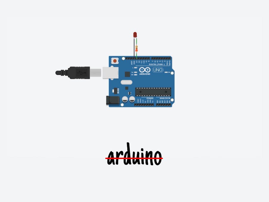
Test circuit presented on the video:
In the Tinkercad Circuits components panel, drag a resistor and LED onto the workplane. Edit the resistor's value by adjusting it to 1000 (1k) ohms in the component inspector which appears when the resistor is selected. Back in the components panel, find and bring over an Arduino Uno board. Click once to connect a wire to a component or pin, and click again to connect the other end. Connect your resistor to either side of the LED. If you connected your resistor to the LED's anode (positive, longer), connect the resistor's other leg to Arduino's digital pin 13. If you connected your resistor to the LED's cathode (negative, shorter leg), connect the resistor's other leg to Arduino's ground pin (GND). Create another wire between the unconnected LED leg and pin 13 or ground, whichever is still not connected.
If you have a physical Arduino Uno (or compatible) board, you may plug an LED directly into pin 13 (positive, longer leg anode) and ground (negative, shorter cathode), because pin 13 actually has a built-in resistor for exactly this testing purpose.
Step 3: Circuit StarterThis is a circuit they think you'll want to make frequently, so it's saved as a circuit starter!
Grab this circuit and code combo any time using the starter available in the components panel (dropdown menu -> Starters -> Arduino). For a more advanced version of this Arduino code, also check out the Blink Without Delay starter, which uses the current time to keep track of blink intervals instead of delay();
Step 4: Order Your Printed Circuit BoardWhen you are sure of your layout, eliminate all bugs, export Gerber files, it's time to order PCB. I usually do it like this:
I go to PCBWay and click "Quote Now", then "Quick Order PCB" and "Online Gerber Viewer", where I upload files for my board, so I can see what it would look like. I go back to the previous tab and click "Upload Gerber File", I choose my file and all parameters are loading themselves, I change only the soldermask color to red. Then I click "Save To Card", provide shipping details, and pay for the order. After two days the tile is sent, and after another two days, it is already on my desk.
Step 5: Thanks!Thanks for your attention and I invite you to check my previous projects!
My Youtube: YouTube
My Facebook: Facebook
My Instagram: Instagram
Get 10 PCBs for only $5: PCBWay


_ztBMuBhMHo.jpg?auto=compress%2Cformat&w=48&h=48&fit=fill&bg=ffffff)


Comments
Please log in or sign up to comment.