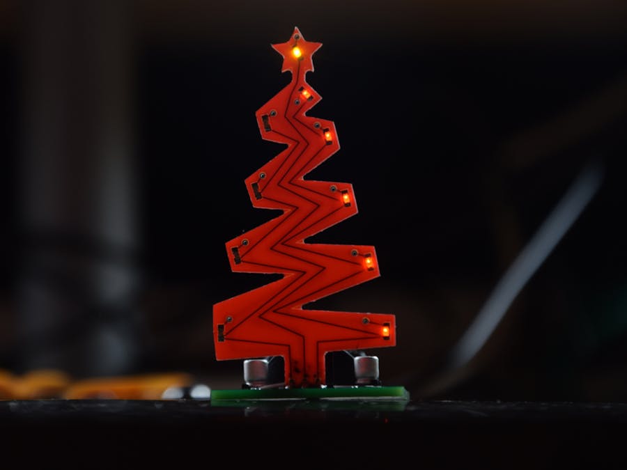
Christmas is only almost 361 days away and most people have Christmas decorations. It's funny. In that case, I will show you the way I made this lovely Christmas tree.
AssumptionsI started, of course, by rethinking the design. Here are the assumptions I followed:
1. Power - a 3V battery
2. Principle of operation - Astable multivibrator
3. Lighting elements - LED 0603
4. Switch - connector
In addition, I decided that all elements would be surface mounted and the whole would consist of a two-part module - the first part will contain the executive electronics, and the second part will have LED diodes. These modules should be connected together by soldering them together.
First PCBI started classically by creating a layout diagram. It is an astable multivibrator circuit, thanks to which the diodes will flash alternately depending on the capacitance value of the capacitors and the resistance of the resistors r1 and r2. Then, using the autorouting option, I created a PCB where the tracks... well, are not at a 90-degree angle to each other. Maybe let's just move on to the second PCB.
Second PCBHere, I started by finding the right shape for my board, converting this file to an SVG file, and uploading it to Fritzing. Then I created a simple circuit on a prototype board consisting of ten diodes. I arranged them on the board, connected them, and added soldering pads on the bottom. Finally, I exported both boards to Gerber files. Then I ordered red and green boards and a stencil for the Christmas tree - as always from PCBWay.
SolderingNow my favorite part - unpacking the package. I have to admit it looks... interesting. Then I prepared myself all the components and tools for soldering. All elements are in the 0603 housing, so no one should have trouble soldering them. After soldering the elements to the first PCB, I prepared a solder paste and a stencil. I immobilized the PCB, applied the stencil, and spread the solder paste. I put the diodes in their places and soldered them using a hot air station. The only thing left to do is solder the two PCBs together and put the battery in its place.
To Sum Up...All in all, this device looked great on a Christmas table and it decorates my desk even better :). The first five people who write a comment under the video on YouTube about what they think about this project will get this kit in the form of self-assembly for free.
My Youtube: YouTube
My Facebook: Facebook
My Instagram: Instagram
Get 10 PCBs for only $5: PCBWay


Comments
Please log in or sign up to comment.