


Hardware components | ||||||
 |
| × | 1 | |||
 |
| × | 1 | |||
 |
| × | 1 | |||
 |
| × | 1 | |||
 |
| × | 1 | |||
 |
| × | 1 | |||
This project was built as the final deliverable for our Embedded System course.
Introduction
In this system we are trying to protect and detect the distance of things using the Ultrasonic module. If one of these things is closest to our module we can do this using the telegram robot and camera module. In the first instance,we connected the camera module to the raspberry pi board then using the telegram robot, we've written the code before,we give the command to our camera module. If a thing has the closest distance to the Ultrasonic module, through the telegram robot, we issue an order to take a photo of that thing and show us to protect our device.
Top-Level Design
Hard Ware
- Ultrasonic module
The ultrasonic HC-SR04 sensor is one of the most commonly used ultrasonic sensors that works well with Arduino. The basis of this ultrasonic module (ultrasound) is similar to a radar or audio detector, detecting the object's characteristics by analyzing the reflection of radio or audio signals. This module receives and analyzes the reflected wave by generating high frequency sound waves.These sensors calculate the distance to the object by calculating the time between sending the signal and taking the reflection. This technology can easily be used to measure the distance and distance between the device and the objects or the ground.This technology can easily be used to measure the distance and distance between the device and the objects or the ground. In these modules, a sensor for transmitting a wave and another sensor to receive the reflection of that wave is located on a board and the electronic interface of the interface makes it very easy to use this module.This ultrasonic module has 4 output bases called Vcc: +5 volts, input: Trig, output: Echo and GND. The HC-SR04 can measure from 2 cm to 400 cm and with a precision of 3 mm.
- Camera module:
The SPI board camera connects directly to the SPI board using the CSI connector. The camera has the ability to capture 5 megapixel resolution and record video at 1080p HD. And has a fixed focus sensor and a resolution of 1944×2292. This module connects via the 15-pin Ribbon cable and connects to the camera's serial interface, which is specifically designed for connecting the cameras. The CSI has the ability to transmit a very high rate of data.The board has a small size of 20x25x9 mm and weighs only 3 grams, so it's a great option for use in projects where the weight and dimensions of the components are high. The sensor has a 5-megapixel resolution and a fixed focus lens that can capture and display static images at 2592x1944 pixels, and supports 1080p @ 30fps, 720p @ 60fps, and 60/90 x 640x480p for video recording.
.
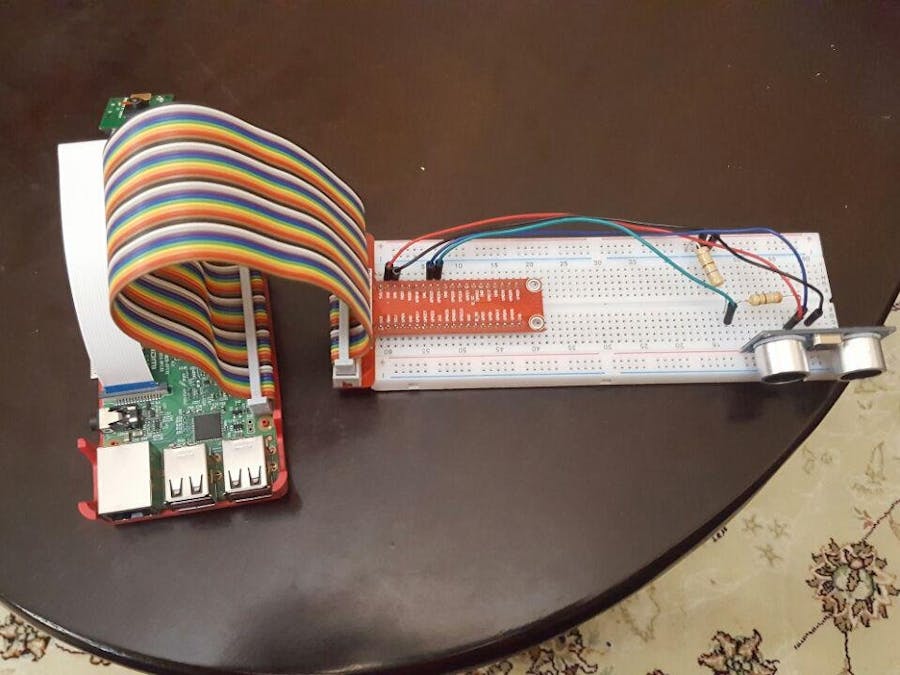
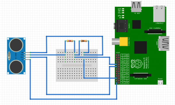
1. Plug four of your male to female jumper wires into the pins on the HC-SR04 as follows: Red; Vcc, Blue; TRIG, Green; ECHO and Black; GND.
2. Plug Vcc into the positive rail of your breadboard, and plug GND into your negative rail.
3. Plug GPIO 5V [Pin 2] into the positive rail, and GPIO GND [Pin 6] into the negative rail.
4. Plug TRIG into a blank rail, and plug that rail into GPIO 23 [Pin 16]. (You can plug TRIG directly into GPIO 23 if you want).
5. Plug ECHO into a blank rail, and plug that rail into GPIO 24.
6. Plug ECHO into a blank rail, link another blank rail using R1 (330 ohm resistor)
7. Link your R1 rail with the GND rail using R2 (475 ohm resistor).
8. Connect the Camera module to the Raspberry Pi board.
9. At the end of work,we have complete project.


Comments
Please log in or sign up to comment.