


Hardware components | ||||||
 |
| × | 1 | |||
 |
| × | 1 | |||
 |
| × | 1 | |||
 |
| × | 1 | |||
| × | 2 | ||||
 |
| × | 1 | |||
 |
| × | 1 | |||
 |
| × | 1 | |||
Software apps and online services | ||||||
 |
| |||||
(This project is being managed here: Project Repository )
The motivation behind the project:This object detection sensor is specially designed to provide security from an unauthorized entry of an object or a body. In your absence, it will not let anyone enter your place unless you allowed him. If someone tries to enter, this sensor will detect it and sound an alarm that will alert your security system and you will be safe from any threat.
Components Description:PIR SensorThis design consists of a PIR (Passive Infrared Sensor). It measures the infrared lights coming from any object, body, or device. Every object and body whose temperature is above absolute zero has some infrared rays inside them. Due to this, detecting infrared rays can be used to detect the presence of any object and the human body. It has an output pin that becomes high when it detects some infrared rays. This sensor consists of three pins:
- Power supply i.e. 5V
- Output pin i.e. becomes high or low after detecting object or body
- Ground pin
The operating voltages of the PIR sensor are from 4.5V to 20V. It provides two types of operation on which they work.
- Repeating Mode: In this mode, the output pin of the sensor remains high after detecting infrared rays even if the object has left the sensing range of detection. You will do it manually low using a potentiometer otherwise it will remain high.
- Non-repeating mode: In this mode of operation, the sensor becomes low when an object or body leaves the sensing area.
This is a voltage regulator IC that provides fixed linear voltages i.e. 5V DC. The threshold limit of this IC is to provide 35V. If any device is having voltages less than or equal to this threshold limit then it will provide a constant 5V. It consists of three pins:
- Input pin Vcc
- Ground
- Output pin Vout i.e. 5V
In this device, the major component is a PIR sensor that typically operates on 5V and this 5V is provided by voltage regulator IC LM7805. The purpose of using the resistor is to limit the current, the relay is used to control any load, the buzzer is used to sound an alarm in case of sensing any object.
The first step is to provide the power supply to the device through the battery. Initially, the PIR sensor will give the output pin as low but as it will observe any presence of infrared rays, transistor BC547 will become active and it will start conducting current, this will activate the relay and buzzer connected to it and the load will start working. The load could be any fan or bulb. The purpose of using the diode is to provide protection to the relay in case of reverse flow of current.
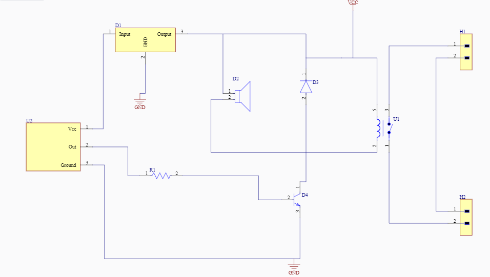
Schematic Design:The first step to creating a board is to design its schematic diagram. I have created my diagram on Altium designer. In this schematic diagram, the input pin of the PIR sensor is connected to the Vcc pin of IC LM7805, and the output pin is connected to the transistor BC547. While the output pin of IC LM7805 is connected to the diode and buzzer. We have two connector headers; one for a connecting load that could be any bulb or fan and the other one is to provide supply through the battery. A relay is connected to a diode, load, and battery side.
I have created my design online on Inventhub, where my all design files of the project are available.
Here you can find the schematic file on Inventhub.
Design Requirements:Before implementing the PCB design, there is a requirement for schematic symbols and footprints. Without these two, design is incomplete. I have created my symbols and footprints and uploaded them on Inventhub which means I have the facility of reusing them in my designs. I only have to download them and I can reuse them instead of designing them again and again.
This is the link where the collection of my components is available Inventhub.
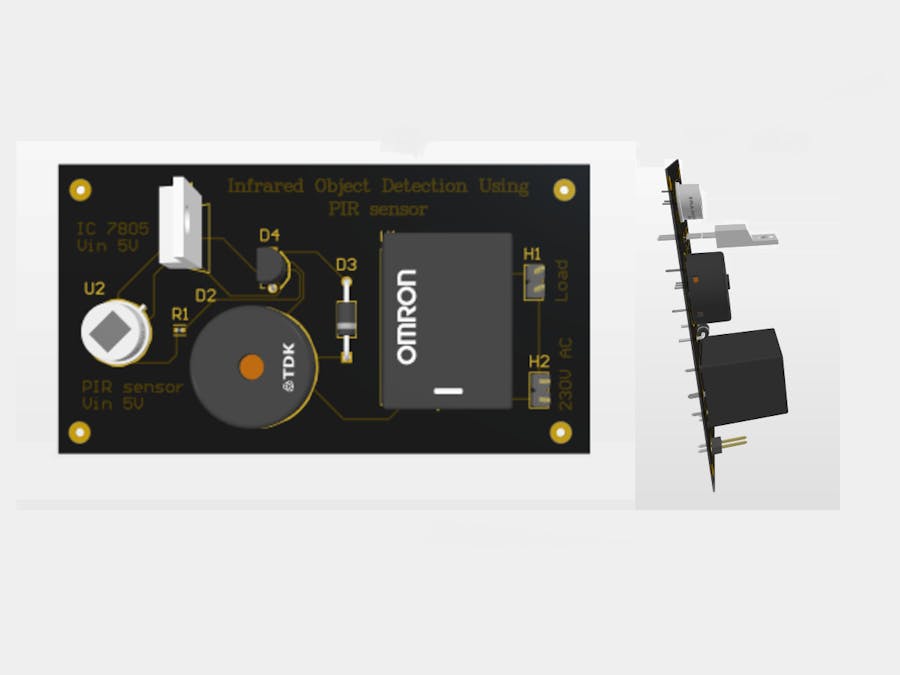
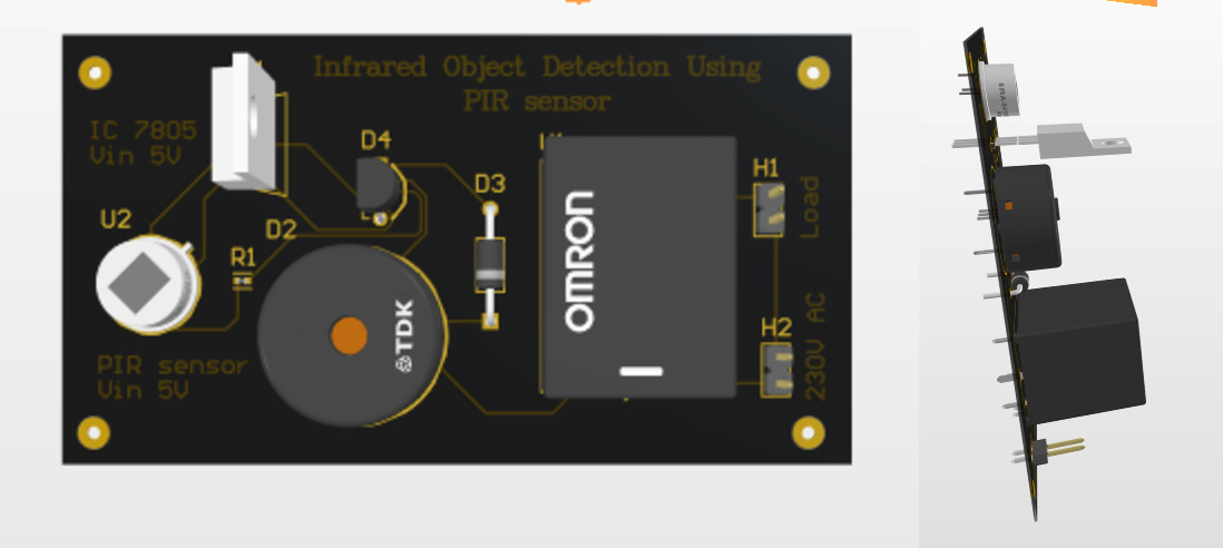
PCB Design:PCB design allows you to view your design in a 3D view. It includes a selection of sizes and layers of the board. Better routing of layers helps in reducing errors in the design. After completing the schematic, I have converted my design to PCB.
This is the link to Inventhub where my PCB design file is available.
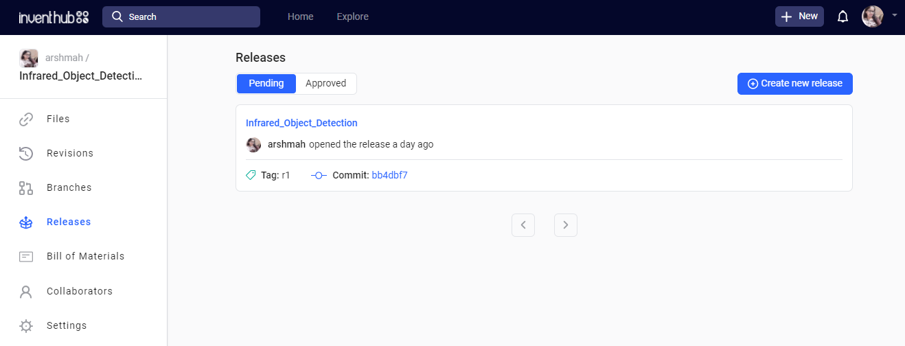
Release File:For manufacturing the board, it is important to have the availability of design files. After completing my design I have created a release file of my project which includes the schematic, PCB files in a zip folder. Instead of visiting the manufacturer, I will send him the link to this release file he will only export it and will be able to fabricate my board.
Here you can find my release file on Inventhub.
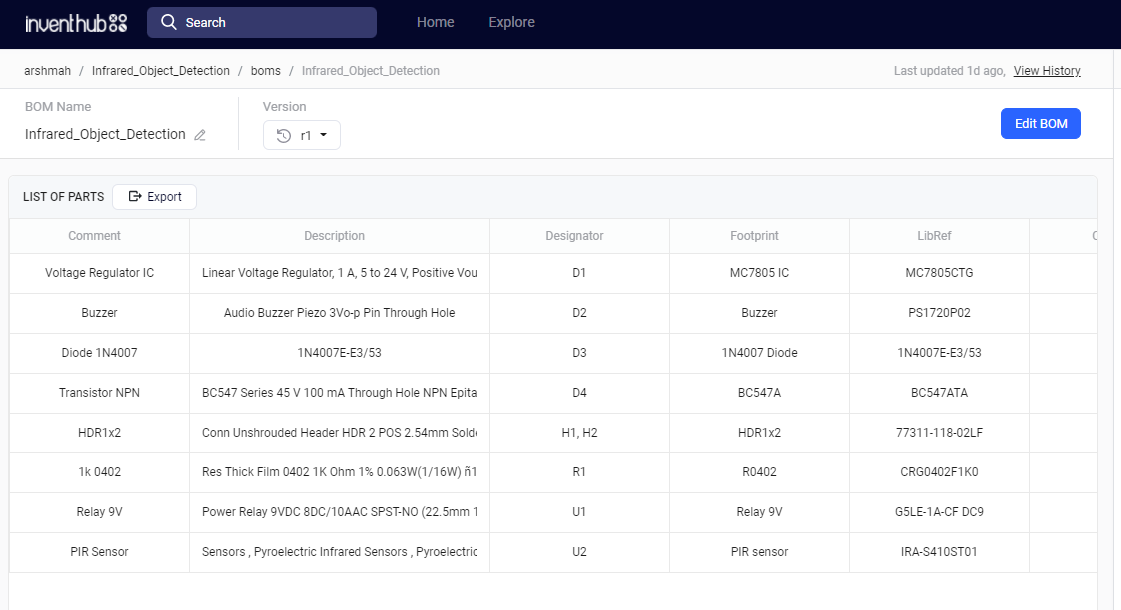
Bill of Materials:I have created a bill of material(BOM) which contain the detail of each component’s footprint, library reference, and quantity. After getting my fabricated board, I need the components to complete my hardware board. I will send the link to this BOM to my component provider. He will download the file and will send me the components of the exact dimensions as I required
Here is the link to BOM on Inventhub.
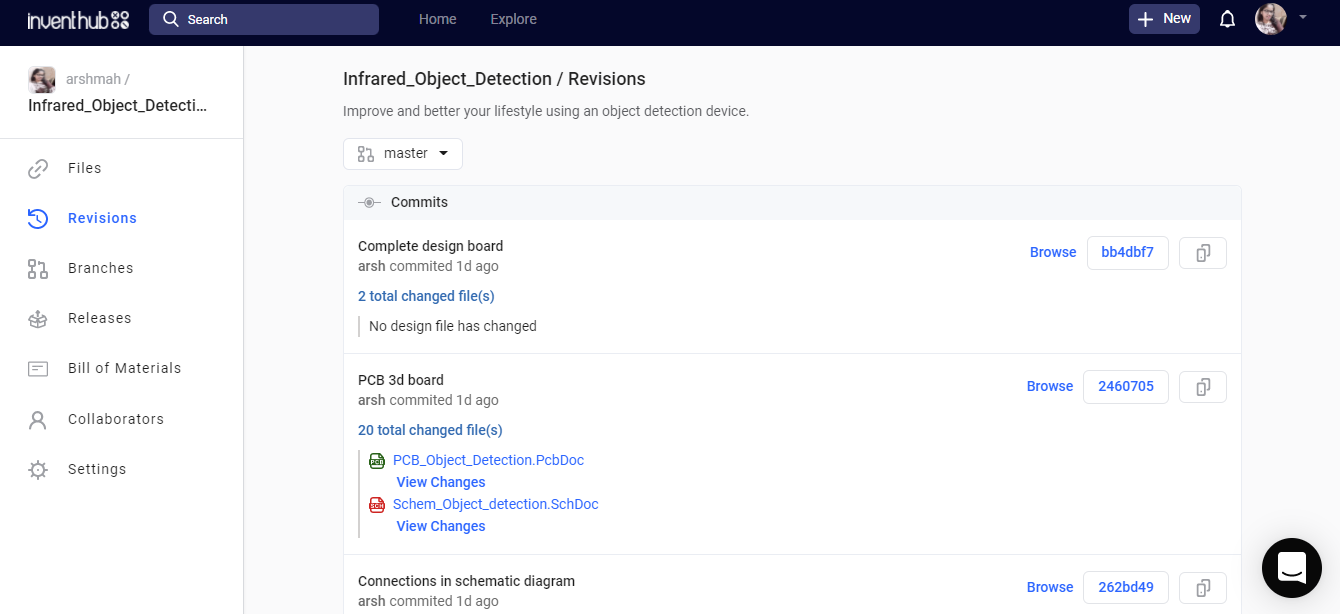
Changes in the Design:If I want to get back the previous version of my design and want to view the changes in my project I can do this online. To do this, I have created the revisions of my project on Inventhub where I have pushed my projects after creating different edits.
Here you can view my revisions in this project on Inventhub.
Feel free to ask any query at arshmah@inventhub.io


Comments
Please log in or sign up to comment.