


Hardware components | ||||||
 |
| × | 1 | |||
 |
| × | 1 | |||
 |
| × | 1 | |||
 |
| × | 1 | |||
 |
| × | 1 | |||
 |
| × | 1 | |||
 |
| × | 1 | |||
 |
| × | 1 | |||
Software apps and online services | ||||||
| ||||||
Hand tools and fabrication machines | ||||||
 |
| |||||
 |
| |||||
Have you ever considered getting an augmented reality headset? Were you also wowed at the possibility of augmented reality and looked at the price tag with a broken heart?
Yes, me too!
But that didn't stop me there. I built up my courage and instead decided to build my own AR headset.
I really felt that augmented reality market is niche and it needs an open market. Makers and developers are the market enablers.
But the problem is that their developer kits are expensive and costs over than $1000. So a normal maker or developer cannot afford it. So I am building this open source platform for augmented reality on both software and hardware so makers and developers can innovate together on it.
Step 1: Continuation...The cost of building this development kit won't cost you more than $20 for a bare minimum design. Now that is where I realised that I need to understand the basic science on how an augmented reality headset works.
I watched a few hands-on demos of few headsets on YouTube and I understood the simple logic behind the display.
One of the uses of this device is to avoid accidents. Most accidents happen in the city due to the distraction caused by phone calls while riding. This could be developed as a device that helps in delivering message notifications and navigates users through the helmet, causing lesser distractions thereby making it a safe ride. Fitted with a GPS and accelerometer, both connected to the cloud, the geographical data collected helps in providing better terrain details for that the rider’s geographical location.
Step 2: Tools NeededParts needed:
- Perf board
- Arduino Nano
- HC 05
- SSD1306 OLED Display
- Buzzer
- Vibrator motor
- Transparent plastic sheets
- Berg pins female
- Wires
- Solder station
- Scissors
- Battery bank
How does an HUD work?
So how does the HUD work? High school physics tells you that light reflects on a mirror, refracts on a semitransparent mirror, and passes through a transparent glass. We will be using exactly that principle here.
How to make the HUD?
- Cut the thick polythene sheet into 5 equal square-shaped pieces.
- Arrange four pieces as a cube with OLED and glue it together.
- Fix the light refractor by placing the sixth piece diagonally inside the cube.
- Glue it such that one surface is facing the OLED display and the other is facing the side of your eye.
- Finally fix the last piece and seal it.
Ta-da!! That is your HUD display. So simple!
Step 4: OLED DisplayI used a Chinese OLED display that works on the SPI bus. It took me almost a day to figure out the data sheet. I found out that the u8lib library is needed to make it work.
Connect the SPI OLED Display to the SPI pin of the Arduino Nano. Now connect this OLED display with a long wire to fit near your eye for easy viewing. Download the library file and extract it into your Arduino library folder. Now uncomment the particular OLED driver in the program to enable your OLED display. Test with different modes in Library Example folder.
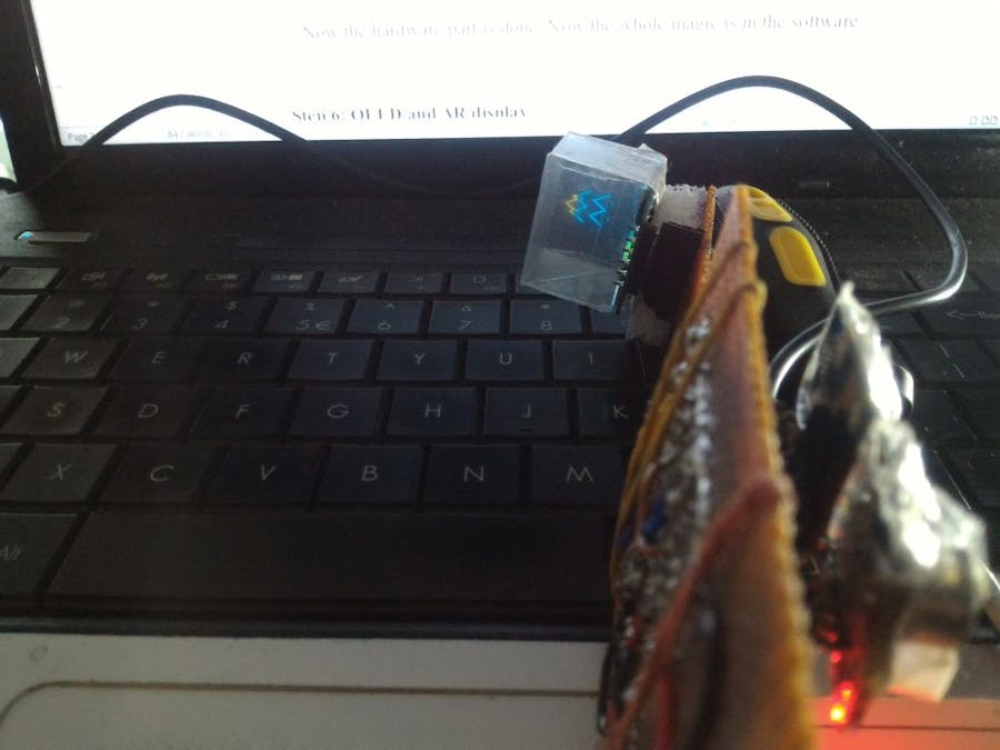
Step 5: OLED and AR DisplayTest the OLED with the AR glass by using the sample code and adjust the display for better viewing experience.
The major problem with this AR display is that we are using a mirror to refract the rays, so the image to be displayed has to be inverted. This requires you to build a library with the inverted alphabet and bitmaps to display it properly.
There are many websites that convert bitmap into HEX code that can be used directly into the OLED library files.
You can use a small concave lens for better focal length.
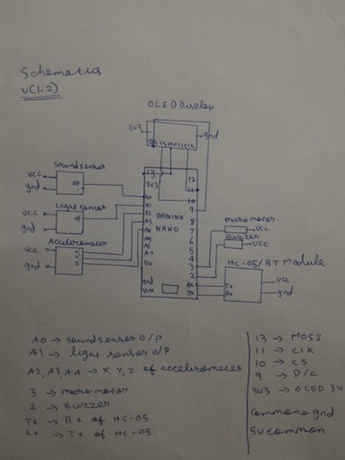
Step 6: Hardware Interfacing with Ard-GNow refer to the schematics here and solder it in a perf board.
It will be a bit tricky to solder if you are a NOOB in soldering. I would recommend that you use as many wires as possible to avoid any mistake while soldering.
Now cut the perf board into two pieces and make it look like an AR glass. Place some foam between the OLED and the perf board to ensure stability. You can also glue it together. Here I have made a bare bone shield for the Arduino Nano where any sensor or device can be interfaced.
I have connected the accelerometer, light sensor and sound sensor for sensor acquisition and can be used for user's application.
Step 7: SchematicClick on the attachment to download the code.
For each function I am sending a number followed by “.” which acts as the end of data and cue to read the next data. It can configure in the ATC Lite Android App.
Check the in-line comment for better understanding of the code.
As for the Android app part, let me be honest. I am not an Android app developer so I haven't implemented the navigation control to it. I just downloaded the ATC lite app and created a custom layout like forward, backward, message and call notification to it. This sends numbers via Bluetooth to the headset.
Click here to download the app and test it.
Step 9: Final testIn the above image, you can see the HUD projecting the display to your eye gear.
Please do give me suggestions and your feedback after trying it out. I would love to hear from you. Feel free to comment below! Let’s talk!


_3u05Tpwasz.png?auto=compress%2Cformat&w=40&h=40&fit=fillmax&bg=fff&dpr=2)


Comments
Please log in or sign up to comment.