The regular mouse has been around for decades, but they require a surface to run. The movement and gesture they can detect is limited to 2D. The 2 dimensional input can be difficult to use when doing 3D design like creating a model for 3D printing. The requirement of a surface limits their usefulness for casual use like navigating Smart TV menus.
Air mouse offers alternative ergonomic arrangements which do not require a flat work surface, potentially alleviating some types of repetitive motion injuries related to posture. The user requires only small wrist rotations to move the cursor, reducing user fatigue.
BackgroundThe following peripherals of K82F will come together to form an Air mouse
- FXOS8700CQ accelerometer
- Touch-sensing input (TSI) module
- Kinetis USB controller in "device" mode
- FlexIO module
Accelerometer
Solid state accelerometer have an electrode that has enough mass to move up and down very slightly when you move or tilt the accelerometer, shown in red. The electrode is supported by a flexible beam. There's a second electrode, shown in yellow, that work together as a capacitor.
The movement of mass produces slight variations in the capacitance which is amplified and refined with the help of support circuitry.
The accelerometer chip used in Freedom board is a FXOS8700CQ. it is a s 3-axis, accelerometer and 3-axis magnetometer combined chip. The chip talks to K82 MCU via I2C interface.
The measured 14-bit accelerometer and 16-bit magnetometer is stored in two 8 bits registers each. The registers are read from software using I2C driver and OR'ed together to build the full reading. Please review this for details.
Touch-sensing input (TSI)
Here is a simplified illustration of how touch input works:
K82 MCU has a builtin touch sensing input module. It implements the capacitive measurement by a current source scan where it charges and discharges the electrode, several times. An oscillator is used to manage scan timing. The result is a 16-bit value when the scan completes.
The two touch buttons are used to send mouse clicks
USB Controller
K82 MCU has a built in USB controller. For our purpose we configure it as USB Human Interface Device (HID). It is part of USB specification covering keyboard, mice and game controllers etc. Most modern operating systems ship with drivers for standard HID mice designs.
Below is an illustration of how the processed values are mapped into the data packet values sent over USB HID interface.
It takes one bit to represent each button, and one byte to represent the movement on one axis. Touch input will be encoded in the first Byte as Bit0 and Bit2 . Movement data is sent on second and third byte.
FlexIO
FlexIO is a smart peripheral that revolutionize the way we think about device IO.
It can do lot of cool stuff but for the purpose of this project, we will use its ability to emulate various serial communication protocols, specifically I2C.
ArchitectureBelow is a simple diagram to show the flow of data in this project:
I selected FreeRTOS to help manage the two parallel operations in this project:
- Sensor Read and normalize
- Gesture Detect and USB Write
To pass data between the two threads, shared memory data storage is used.
Hardware SetupPin connections
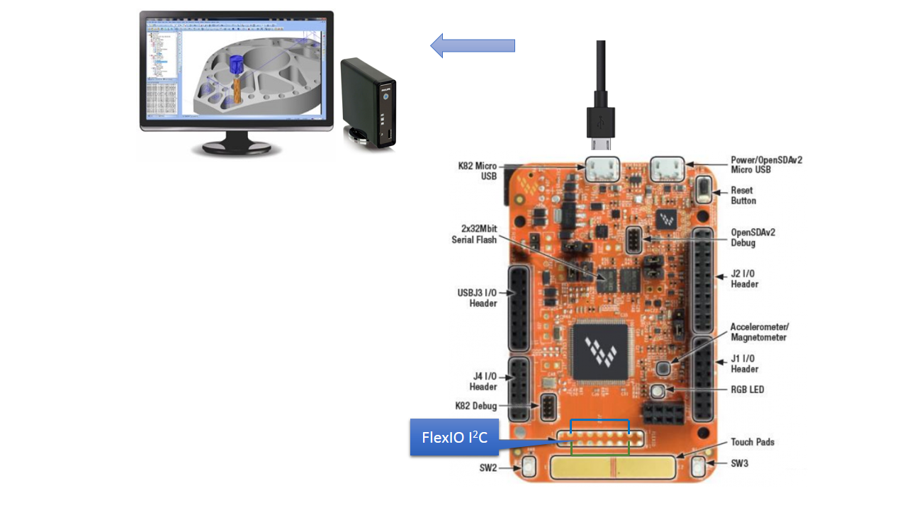
In order to connect FlexIO pins with the I2C pins of the accelerometer/magnetometer, locate J12 header and make the following connections, As shown in picture below.
- Pin 3 connected to 15
- Pin 4 connected to 16
USB Debug
The K82F board is shipped with MBED debug interface. This interface is not supported in Kinetis Design Studio debugger that is used in this project. In order to debug, I have to install the J-Link OpenSDAv2.1 firmware. Below are the steps:
- With the board unpowered, hold down the Reset button on the FRDM-K82F and plug in a micro-B USB cable into the “SDA USB” USB port on the board.
- Release the Reset button
- The board will enumerate as a “BOOTLOADER” driver
- Download
04_OpenSDA_FRDM-K82F.binfrom Segger website
- Drag and drop the downloaded .bin file into this drive.
- Do a power cycle, and now the board will be running the JLink OpenSDA application
- You should now notice a new COM port in your PC's device manager.
Debug console
Open the terminal application on the PC like PuTTY or Minicom and connect to the debug COM port. Terminal settings are:
- 15200 baud rate
- No parity
- 8 data bits
- 1 stop bit
Full debug instructions are here.
Software Setup- Install Kinetis SDK and Kinetis Design Studio by following instructions on this page
- Clone the repo to
<sdk_install>/SDK_2.0_FRDM-K82F/boards/frdmk82f/usb_examples/backup the existingusb_device_hid_mousefolder
- Import the project in KDS by going to
File->Import
- Select
Existing Projects Sets
- Browse to the import location and press
Finish
- Select the project and click Build from the toolbar
- After a successful build the console should look as following.
- Make sure micro-B USB cable is in the “SDA USB” USB port on the board
- Select the project and Click Debug toolbar icon
- Select Jlink configuration and select OK. Make sure
- Insert micro-B USB cable is in the usb port next to “SDA USB” and connect to your PC. It should enumerate as USB HID device.
Pick your K82 board up and move it around and notice the cursor update. The Touch pads works as Left/Right Clicks.
Advanced Gesture DetectionThe default gesture detection routine I wrote is just a "Proof of Concept". When you move your board, the pointer updates accordingly, when you tap on the two Touch Pads, it registers as a Left or Right Click.
The following gestures are available but not currently in use:
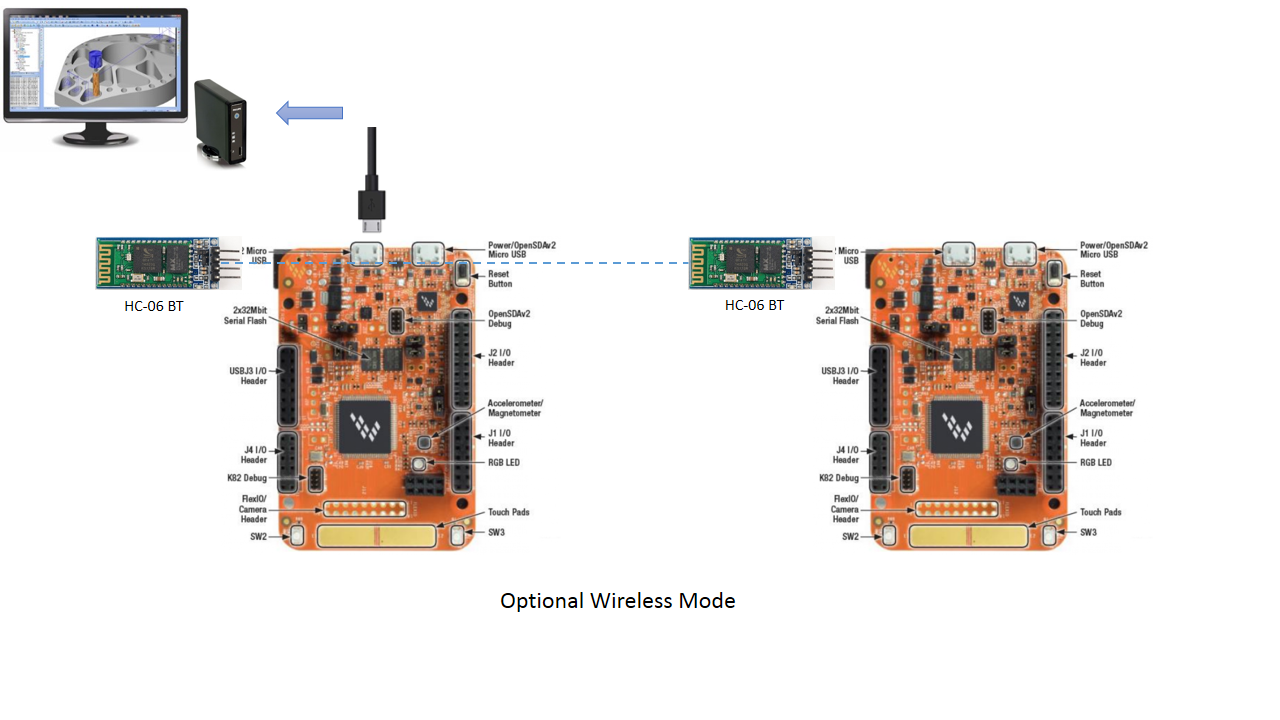
Air mouse that we just built is really fun to use if it is wireless. Wireless configuration can be built with two F82K boards communicating over Bluetooth. One connects to the PC and other one you hold in your hand and provides accelerometer. The revised architecture looks like:


Comments
Please log in or sign up to comment.