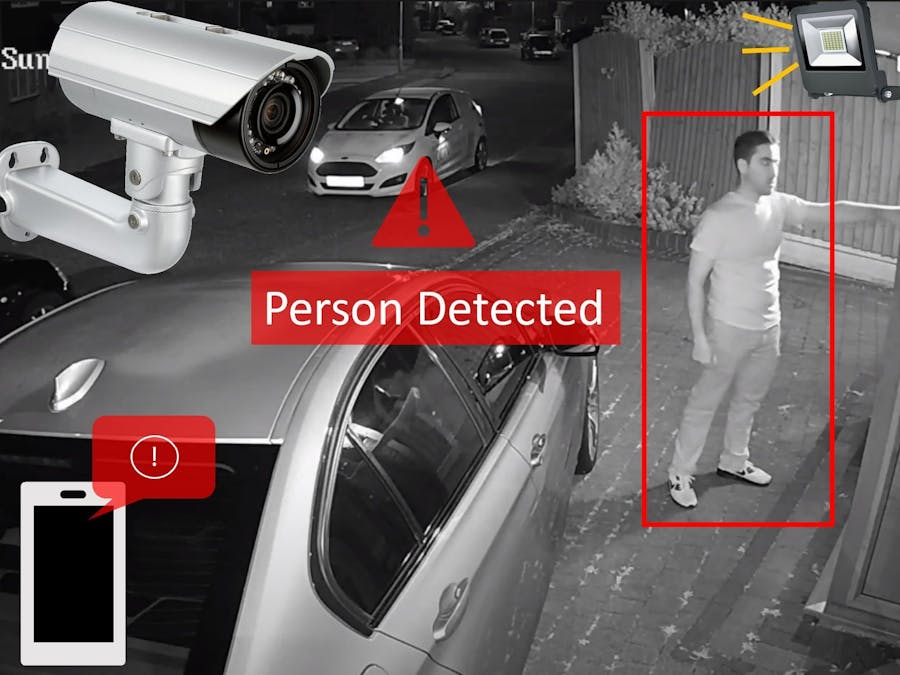
As part of home renovation, I recently installed security cameras and lights around the house.
Modern IP cameras come with motion detection capability out of the box. What I learned the motion detection may trigger for pets and stray cats generating lots of false alerts, secondly the camera software ecosystem is locked. It was limited to only a handful of actions supported in proprietary vendor app. I was looking for example a python API or SDK, and I was disappointed.
I noticed that cameras are ONVIF compatible. This means that I can process the video stream in Python OpenCV as RTSP and do whatever I want with the results. Hence this project was born.
ArchitectureThere is lot of flexibility in how you can build the project to suit the kind of hardware available to you. You can adopt it to suit the cameras and lights installed at your location.
Here is how the completed hardware setup looks like during my prototyping stage.
Embedded Platform
You can use any Raspberry Pi 4 Model B compatible hardware. I used reTerminal because the built-in LCD is compact and makes troubleshooting easier. eMMC storage provides fast bootup times. It comes pre-installed with a heatsink!
If you plan to use normal Raspberry Pi 4, be sure to install a heatsink since the code is CPU intensive.
For those who don't know the difference between Raspberry Pi Compute Module (CM) vs regular Raspberry pi is that the CM is designed for industrial and embedded markets. One can think of CM as stripped-down version of normal Raspberry Pi with no ports.
I selected Raspberry Pi 4 platform because its the most powerful Raspberry Pi at the time of writing. It supports TFLite XNNPACK optimization, able to run MobileNet SSD model at 12 fps with 64bit OS.
Level Shifter
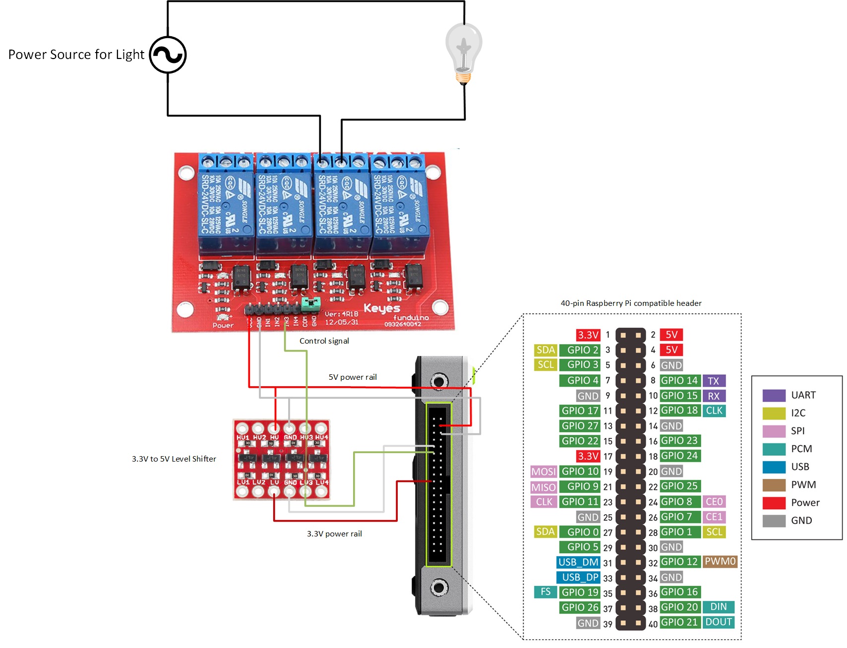
Only required if your relay board is designed for 5V control input. it steps up 3.3V to 5V required for the relay. It also supports step down 5V signals to 3.3V but is not used in my project. If you have a relay that operates let's say via I2C then this the bi-directional conversion of the level convertor is really useful.
The Level shifter that I used is couple years old and longer in production. You can grab one from SparkFun which is functionally the same with only difference of pinout.
Camera
You can use any camera that is able to provide RTSP steam to OpenCV. The minimum image resolution is 300x300 pixels. Any CCTV camera you find today would be sufficient. The software also supports USB camera with command line arguments, but I did not perform a lot of testing because my home security setup consists of IP cameras only.
The camera I used is powered over ethernet. For this you need a PoE compatible ethernet switch and CAT-6 cable connection.
Light
I'll recommend using a 12V power supply and 12V light for prototyping. Once project is completed hire a professional electrician for connection to the household electricity. Be careful electricity can be very dangerous!
Relay
If you can find a replay HAT that connects directly to Raspberry Pi, that is ideal. If you are like me, you might have Arduino compatible relays that operates at 5V. A typical good relay, is generally spec’d to close at 75% to 120% of the nominal voltage, so 3.75V for a 5V relay. So, 3.3V from GPIO might close a particular 5V relay, but you probably can’t count on it. Check the datasheet of the relay that you have.
I feel more comfortable using a level shifter in-between which makes the operation safer and reliable.
Relay has a normally open NO pair and normally close NC pair. I used the NC but you can use either as long as you adjust the software.
Wiring
I made the following connections on the 40pin Raspberry Pi header:
- Pin 5 - 5V supply for level shifter and relay
- Pin 11 - GPIO 17 - control signal for relay
- Pin 17 - 3.3 V supply for level shifter
- Pint 9, 6 - Ground
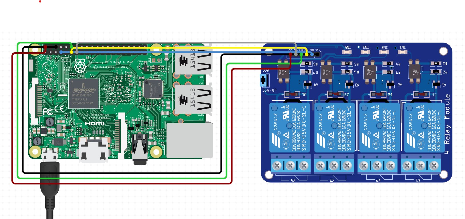
In this picture I've also connected pin7, 13 and 15 to relay 1, 2 and 4 via level shifter for future expansion but not used them during prototyping.
One wire from light power supply goes directly to the light. The other wire goes through the relay which then effectively becomes software controlled light switch.
Testing hardware wiring
I tested if all hardware is wired correctly with the following commands on reTerminal console:
sudo -i
# enable GPIO
echo 17 > /sys/class/gpio/export
# Configure GPIO as output
echo out > /sys/class/gpio/gpio17/direction
# Toggle GPIO ON/OFF in a loop
while true; do echo 0 > /sys/class/gpio/gpio17/value; sleep 2;echo 1 > /sys/class/gpio/gpio17/value; sleep 2; done
# Ctrl-C to exit.
This is how it looks:
Software SetupCamera Configuration
The IP camera that I used has web interface accessible. First step is to add a user/password for RTSP stream such as shown below.
If your camera supports multiple streams then select a low-resolution stream for the consumption of Raspberry Pi. The Neural Network used expects an image size of 300x300. A smaller resolution stream takes less bandwidth and is faster to process by OpenCV.
OS Installation
To get the best performance out of TensorFlow, install latest stable release of 64bit Raspberry PI OS. The instructions for installing OS to reTerminal are here
OpenCV and FFmpeg
On reTerminal console, use command:
$sudo apt install ffmpeg python3-opencv
check installation:
$python3 -c "import cv2; print(cv2.__version__)"
4.5.1
TensorflowLite
Install TensforFlow Lite with XNNPACK optimization by following instructions on this page.
Running MobilenetSSD model pre-trained on COCO dataset looks like this:
notify run
In order to get notification to smart phone, install and configure notify run by following this page.
Software Versions
OS: Debian bullseye
Kernel: Linux reTerminal 5.10.92-v8+ #1514 SMP PREEMPT Mon Jan 17 17:39:38 GMT 2022 aarch64 GNU/Linux
Python: 3.9.2
OpenCV: 4.5.1
TensorFlowLite: 2.8.0
notify-run: 0.0.14
Running the Code:
- Log into reTerminal and create folders ~/ssd and ~/ssd/models
- Download file mobilenetv2ssd-sync-ipcam.py from the github repo.
- cd to ~/ssd/models and download pre-trained model, use command:
wget https://github.com/PINTO0309/TensorflowLite-bin/raw/main/models/mobilenet_ssd_v2_coco_quant_postprocess.tflite
- Open file mobilenetv2ssd-sync-ipcam.py in an editor and update IP address user and password for your camera, located in the start of the file.
- Review RTSP URL and check camera port, path, channel, subtype and other arguments for your IP Camera. For the camera model that I used subtype 0 corresponds to FullHD H.265 format while subtype 1 corresponds to VGA H.264.
If you want to check if the RTSP URL is correct you can install VLC player on your PC or RaspberryPi and go to File-> Open Network Stream and paste the URL. Now you should be able to view live stream in VLC.
- Other values you might want to configure are minimumLightDurtation that controls the number of seconds the light statys ON after a positive detection and minimumNotificationDelay that limits the rate at which notifications are pushed to the smart phone.
- Open console and cd to ~/ssd and use the following command to run the code. The width, height below represents the VGA resolution of the video stream.
DISPLAY=:0 python mobilenetv2ssd-sync-ipcam.py --camera_width 640 --camera_height 480


_3u05Tpwasz.png?auto=compress%2Cformat&w=40&h=40&fit=fillmax&bg=fff&dpr=2)

Comments
Please log in or sign up to comment.