Couple months back I bought a new 10th gen Honda Civic. The trim offered in my region lacked all ADAS features. Being an engineer with embedded systems background, I decided to build one myself.
Most ADAS combine camera with RADAR or LIDAR. I however only had camera to start with. It turned out I can do some basic tasks like Lane detection and departure warning but not much else, till the day Walabot arrived. Cameras are great of classification and texture interpretation but they struggle with 3D mapping and motion estimation. For automotive applications, Walabot can be used as a short range RADAR.
Let's see how this performs!
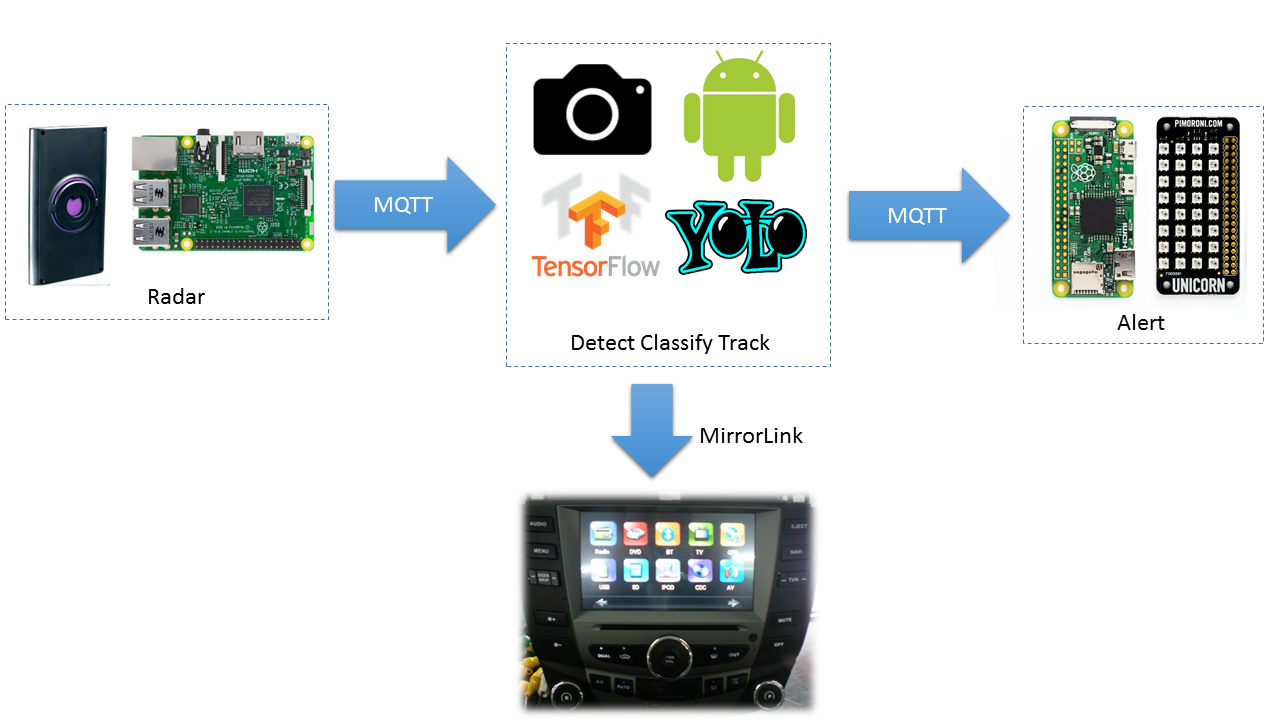
ArchitectureIntegration of Camera and Walabot's data is shown below.
Generally we combine sensory data in a way that the resulting information has less uncertainty than would be possible when these sources were used individually.
Using different sensor types also offer redundancy in situations where one type of sensors would fail. That failure or malfunction can be caused by nature or it can be deliberate e.g jamming a RADAR.
A camera generally has trouble in fog, rain, sun glare and low- light. RADAR on the other hand, lacks the resolution of cameras. but it is great for measuring distances and looking through rain and fog. RADAR and camera can complement each other.
My algorithm raises an alert, if both Camera and Walabot has detected an object of interest in the same spatial coordinates
This is high level diagram of how data flows between major components.
Our RADAR is built using Walabot connected to a Raspberry PI v2 and communicating by MQTT over WiFi. I used WiFi hotspot built into the IVI unit. You can use a standalone hotspot but they tend to perform poor in automotive environment.
Background
Walabot gives you x-ray like vision but it does not use x-ray. Walabot has an array of linearly polarized broadband antennas that operate in frequency range: 3.3-10.3 GHz for the FCC model and 6.3-8.3 GHz in CE model.
If you are not familiar with Antenna Theory, the term polarization comes from the standing wave notation. In RF case, it means the orientation of Electric and Magnetic Field w.r.t direction of propagation. Linear polarized antennas typically have greater range due to the concentrated emission. I guess this makes sense for the Walabot case since we want to maximize the field of view.
At the heart of the Walabot there is a proprietary Vayyar VYYR2401 System-on-Chip for signal generation and reception. To connect via USB it uses Cypress FX3 controller.
Walabot can be configured in different modes for different use-case. They call it "scan profiles".
- Short-range: penetrative scanning inside dielectric materials such as walls.
- Sensor: High-resolution images, but slower capture rate. Good for distance scanning:
- Sensor Narrow: Lower-resolution images for a fast capture rate. Useful for tracking quick movement.
I choose to use "Sensor" scan profile.
When Sensor profiles is used, Walabot processes and provides image data in a Spherical coordinates system. Ranges and resolution along radial distance and Theta and Phi angles.
Your application can convert spherical coordinates to Cartesian ones, using the formulae:
Once you are in Cartesian (X-Y-Z) axes, then question is which side is up? The Walabot's center is the origin, and their positive directions are:
When Walabot is in its plastic case, USB connector side is the bottom.
You may ask the question why Raspberry PI v2? We are limited by Walabot SDK. The SDK is only available for x86 and Raspberry PI. I tried with Raspberry PI Zero first but the CPU was maxing out and I was loosing real-time detection capability. When I traded up to a Raspberry PI v2, things became smoother. I still think we loose samples but it seems to be workable for my use case.
RADAR Hardware Setup
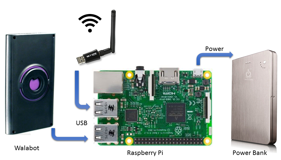
Wire up everything as shown below. Make sure to use a 2A power source!
Wrap everything in waterproof cover and install in the font of the vehicle.
RADAR Software Setup
- You need a MicroSD Card with Raspbian. Either buy one or program using these instructions.
- Boot Raspberry Pi and install updates. Instructions here.
- WiFi connection instructions are here.
- You need to modify boot arguments to increase USB current. Open a console shell to your RPI and edit like this:
$sudo nano /boot/config.txt
- Add the following
max_usb_current=1
safe_mode_gpio=4
- Reboot
- Open a console shell to your RPI and use these instructions to install Walabot SDK.
$wget https://walabot.com/WalabotInstaller/Latest/walabotSDK_RasbPi.deb
$sudo dpkg -i walabotSDK_RasbPi.deb
- Connect your Walabot via provided USB cable. Run command
$ walabot-diagnose
- It should complete without errors. Power issues frequently cause this to fail.
- Copy script Walabot_RPI /PedestrianDetect.py to any location on your RPI
- Open PedestrianDetect.py in your favourite editor and look for a line that reads "mqttc.connect". Insert address of your MQTT broker. For testing on your desk, you can use "iot.eclipse.org" but the round trip time will be too big for realtime usecase. You will need to run MQTT broker on your LAN. I choose to do this on my Raspberry Pi Zero. Instructions further down this post.
- Run it like:
$python PedestrianDetect.py
Eventually you will need to make this autorun on boot up. You can read about all the different ways to do that from here. I choose to go about this by modifying /etc/rc.local.
Walabot input parameters
I used Sensor profile. When Sensor profiles is used, Walabot processes and provides image data in a Spherical coordinates system. Ranges and resolution along radial distance and Theta and Phi angles. This translates to the following Walabot APIs:
- SetArenaR
- SetArenaTheta
- SetArenaPhi
All of these require specifying constants. This is very important, because the fine tuned parameter can make a huge difference in the results you get. The values that worked for me are as follows:
    minInCm, maxInCm, resInCm = 10, 100, 2
    minIndegrees, maxIndegrees, resIndegrees = -20, 20, 10
    minPhiInDegrees, maxPhiInDegrees, resPhiInDegrees = -45, 45, 2
Your RADAR setup is now done,.
Camera subsystemBackground
There are following challenges with using camera for our use-case:
- Various style of clothing in appearance for pedestrians.
- The presence of occluding accessories on cars and persons.
- Different possible articulations
- Frequent occlusion between cars and or pedestrians
I used TensorFlow which was originally developed by researchers and engineers working on the Google Brain Team within Google's Machine Intelligence research organization for the purposes of conducting machine learning and deep neural networks research. For my application it works on a frame size of 640x480 from camera. I've noticed that it does not work very well if device is rotated, e.g from portrait to landscape.
I have used YOLO generated graphs with TensorFlow because it is able to run on a Android mobile and still able to get decent detections in realtime.
How YOLO works?
Yolo apply a single neural network to the full image. This network divides the image into regions and predicts bounding boxes and probabilities for each region. These bounding boxes are weighted by the predicted probabilities.
Yolo speed up comes from using a joint training algorithm that allows training object detectors on both detection and classification data. Yolo leverages labeled detection images to learn to precisely localize objects while it uses classification images to increase its vocabulary and robustness.
Block Diagram
The following steps happen on the Android side:
- Image acquisition
- Detecting an object rectangle by Yolo
- Classifying the object rectangle by Yolo
- Tracking this object by TensorFlow's Multi-box tracker
- Comparing Tracked object location with Walabot's reported location.
- Raise alert if both coincide in same spatial coordinates
Here is block diagram for the key classes involved in combining sensor data and generating alert when a hazard is detected.
Hardware setup
You will need a mid-range Android device running at least version 5.0 Lollipop. A decent camera is a plus. I tried on Samsung Galaxy A3 and Huawei P9. Both worked great. You don't need any extra hardware with that, may be except a data cable and a stand to keep the phone upright on the dashboard.
Enable WiFi on your Android device and connect to the same hotspot where your Raspberry Pis are connected.
Keep your AC vents towards the windshield. The Android phone tend to get overheat in hot sunny day.
Software Setup
- Install Android Studio on Ubuntu 16.04 LTS desktop. Instructions are here.
- Clone my projects's git repo.
- Clone DarkFlow.
- Open DetectorActivity.java in your favourite editor and look for a line that reads "NetworkFragment.getInstance". Insert address of your MQTT broker. The syntex is tcp://<ip address>:1883
- For testing on your desk, you can use "iot.eclipse.org" but the round trip time will be too big for realtime usecase. You will need to run MQTT broker on your LAN. I choose to do this on my Raspberry Pi Zero. Instructions further down this post.
- Follow the build steps mentioned on this page.
- The bazel build will download TensorFlow related data files automatically. However the YOLO graph is not included with TensorFlow and must be manually placed in the assets/ directory.
- Download tiny-yolo-voc.cfg and tiny-yolo-voc.weights from http://pjreddie.com/darknet/yolo/
- Convert Tiny Yolo via DarkFlow. The command I used:
$./flow --model cfg/tiny-yolo-voc.cfg --load bin/tiny-yolo-voc.weights --savepb --verbalise=True
- Enable developer options on your Android Phone and download and run .apk. The instructions are here.
- Setup and enable MirrorLink on you device to mirror the display to your IVI head unit. Samsung's instructions are here. Please follow your IVI unit documentation. My Honda Civic required me to connect my phone to IVI unit via USB and start E-Link application, then follow on-screen instructions.
Once a hazard is detected, Android TensorFlow application will publish an Alert. This is done on the same MQTT server with topic "walabot/alert". This gives great flexibility on how you choose to react to the alert. You can potentially have multiple devices respond to this if they are all subscribed to the same topic.
I choose to blink red LEDs.
Hardware Setup
- Solder headers on Pimoroni pHat.
It will fit nicely on a Raspberry Pi Zero.
- Insert a USB WiFi dongle. You may need a micro-B USB to USB A female cable.
- Attach a PowerBank or your Pi Zero or plug into a USB charging ports of your car.
- You Alert subsystem is assembled.
Software Setup
- You need a MicroSD Card with Raspbian. Either buy one or program using these instructions.
- Boot Raspberry Pi and install updates. Instructions here.
- Connect to the WiFi hotspot built into the IVI unit. You can use a standalone hotspot but they tend to perform poor in automotive environment. Instructions are here.
- Take a note of the IP address assigned to this. If you are planning to use this Raspberry Pi Zero as MQTT broker, then you will need this IP.
- Open a console shell to your RPI and use these instructions to install Pimoroni SDK.
$curl https://get.pimoroni.com/scrollphat | bash
- Copy script Unicorn_RPI /MqttAlert.py to any location on your RPI
- Install MQTT broker by following command:
$sudo apt-get install mosquitto
- If you are using a different MQTT server then open MqttAlert.py in your favourite editor and look for a line that reads "client.connect ". Insert address of your MQTT broker.
- Run it like:
$sudo python MqttAlert.py
Eventually you will need to make this autorun on boot up. You can read about all the different ways to do that from here. I choose to go about this by modifying /etc/rc.local.
Alert subsystem is ready!
DisclaimerSystems like Pedestrian Detection are not a replacement for an attentive driver.
Walabot does not come in a casing that is suitable for prolonged outdoor use.

_copy_P5AWOdT4dX.png?auto=compress%2Cformat&w=48&h=48&fit=fill&bg=ffffff)


Comments
Please log in or sign up to comment.