


Hardware components | ||||||
 |
| × | 1 | |||
 |
| × | 1 | |||
 |
| × | 1 | |||
 |
| × | 1 | |||
Software apps and online services | ||||||
| ||||||
 |
| |||||
| ||||||
_4YUDWziWQ8.png?auto=compress%2Cformat&w=48&h=48&fit=fill&bg=ffffff) |
| |||||
INTRODUCTION
Due to the tremendous market growth in the field of IoT products,There is an increase in demand for low-cost Smart Switch Control Systems (SSCS) that can remotely control home devices in residential environments using mobile applications or websites. Hence in this project,we are developing a product called smart extension cord which is an improved version of ordinary extension cord,having Energy Management and IoT based power outlet(socket) controlling system in it. This product can be controlled from anywhere using a smart device having internet connectivity.it also supports direct wifi communication when internet connection fails. User can monitor live power consumption through extension cord sockets & approx electricity cost via web app and 16x2 display attached to the product. User have the ability to set a maximum load limit, hence beyond that limit,the system will automatically shut down. Also, the timer-based operation minimizes power wastage due to socket remaining ON even after usage.
OBJECTIVE OF THE PROPOSED SYSTEM
Objective of the project is to design and set up a smart extension cord with following features.
• Load control
• Timer-based On/Off scheduling
• Live power consumption & approx electricity cost Monitoring system
• Support both online and offline operation
• Low cost
• Surge protection
BLOCK DIAGRAM
Block Diagram Description
This block diagram explains the principal parts and functions of the project. The main block contains nodemcu esp8266,which is wifi enabled microcontroller having Tensilica Xtensa 32-bit LX106 RISC microprocessor[5].NodeMCU is an open-source firmware and development kit that helps to prototype or build IoT products.It can operate in two modes.station mode and access point mode.while station mode nodemcu needs a router(as an access point) having internet connectivity in order to communicate with MQTT broker[3]. But in access point mode, it acts like a hotspot(access point). Hence the user needs to connect their smart device into this product through wifi in order to communicate with it.This facilitates the user to control the product through online and offline.
Blocks at left side are equipped with sensory parts for measuring main voltage and load current through the system.For that,we use MCP39F521 24-Bit single-phase AC/DC power monitoring IC made by microchip.It can measure Vrms,Irms and output Real,Reactive,Apparent power, energy, with accuracy of 0.1% ,and support 12C communication through which we collect the data into mcu and displays it through 16*2 LCD display and adafruit dashboard/local web page.Also a 230 VAC to 5 VDC power supply is used to power Nodemcu,Relay and LCD display modules.
16*2 LCD display block outputs various informations and acknowledgements passed by the microcontroller. Through which,user can monitor device status,local web server ip address,Instantaneous power,Electricity Cost.The top side block represents the power outlets where end users can connect their appliances.A 4 channel relay is associated with this block in order to turn on and off main supply voltage going to the outlets and is managed by mcu control signals.[2][3][4]
HARDWARE DESCRIPTION
NODE MCU
NodeMCU is an open-source IoT platform. It is a development board featuring the popular ESP8266 Wifi chip. As it turns out, you can program the ESP8266 just like any other microcontroller. Its obvious advantage over the Arduino or PIC is that it can readily connect to the Internet via Wi-Fi. However, the ESP8266 breakout board has limited pins although the chip itself has a lot of output ports. The NodeMCU solves this problem by featuring 10 GPIO pins each capable of using PWM, I2C and 1-wire interface. The firmware uses the Lua scripting language. It is based on the eLua project and built on the Espressif Non-OS SDK for ESP8266. It uses many open source projects, such as lua-cjson,and spiffs.[5]
This ESP8266 development board really looks like an Arduino Nano. Speaking of Arduino, another advantage of this board is that you can connect it directly to your PC or Mac and program it like an Arduino.
ESP8266EX is embedded with Tensilica L106 32-bit microcontroller (MCU), which features extra low power consumption and 16-bit RISC. The CPU clock speed is 80MHz. It can also reach a maximum value of 160MHz. ESP8266EX is often integrated with external sensors and other specific devices through its GPIOs; codes for such applications are provided in examples in the SDK.
ESP8266EX Wi-Fi SoC is embedded with memory controller, including SRAM and ROM. MCU can visit the memory units through iBus, dBus, and AHB interfaces. All memory units can be visited upon request, while a memory arbiter will decide the running sequence according to the time when these requests are received by the processor. According to our current version of SDK provided, SRAM space that is available to users is assigned as below:
• RAM size < 36 kB, that is to say, when ESP8266EX is working under the station mode and is connected to the router, programmable space accessible to user in heap and data section is around 36kB.)
• there is no programmable ROM in the SoC, therefore, user program must be stored in an external SPI flash
MCP39F521 I2C Power Monitor IC
The MCP39F521 is a highly integrated, complete single-phase power-monitoring device, designed for real-time measurement of input power for AC/DC power supplies, power distribution units, consumer and industrial applications. It includes dual-channel delta-sigma ADCs, a 16-bit calculation engine, EEPROM and a flexible two-wire I2C interface. An integrated low-drift voltage reference with 10 ppm/°C in addition to 94.5 dB of signal-to-noise and distortion ratio (SINAD) performance on each measurement channel allows for better than 0.1% accurate designs across a 4000:1 dynamic range.Package Type:28-Lead Plastic Quad Flat, No Lead Package (MQ) – 5x5 mm Body [QFN] Land Pattern With 0.55 mm Contact Length
4 Channel Relay Module
It is a LOW-Level Trigger 4 Channel Isolated 5V 10A Relay Module, and each channel needs a 15-20mA driver current. A wide range of microcontrollers such as Arduino, AVR, PIC, ARM and so on can control it. It is also able to control various appliances and other types of equipment with a large current. Relay output maximum contact is 250VAC 10A and 30VDC 10A. One can connect a microcontroller with a standard interface directly to it. Red working status indicator lights are conducive to safe use. It has a wide range of applications such as all MCU control, industrial sector, PLC control, smart home control. This relay module features 4 x 5V relays rated at 10A/250V each. It is designed to switch up to 4 high current (10A) or high voltage (250V) loads with the help of a microcontroller. Each relay can individually switch on/off by an opto-isolated digital input, which can connect directly to a microcontroller output pin. It only requires a voltage of approx 3.3V to switch the inputs on but can handle input voltages up to 5V. This makes it ideal for 3.3V to 5V devices.
Operating Principle
See the picture below: A is an electromagnet, B armature, C spring, D moving contact, and E fixed contacts. There are two fixed contacts, a normally closed one and a normally open one. When the coil is not energized, the normally open contact is the one that is off, while the normally closed one is the other that is on. 4 www.handsontec.com Supply voltage to the coil and some currents will pass through the coil thus generating the electromagnetic effect. So the armature overcomes the tension of the spring and is attracted to the core, thus closing the moving contact of the armature and the normally open (NO) contact or you may say releasing the former and the normally closed (NC) contact. After the coil is de-energized, the electromagnetic force disappears and the armature moves back to the original position, releasing the moving contact and normally closed contact. The closing and releasing of the contacts result in power on and off of the circuit.
5V to 3.3V Logic Converter
A bi-directional Level Converter- 4 Channel is a small device that safely steps down 5V signals to 3.3V AND steps up 3.3V to 5V at the same time. This level converter also works with 2.8V and 1.8V devices.This Level Converter features four high speed bi-directional 4 channels, allowing for safe and easy communication between devices operating at different logic levels.The logic level converter circuit convert signals as low as 1.8 V to as high as 5 V and vice versa, and its four channels are enough to support most common bidirectional and unidirectional digital interfaces, including I²C, SPI, and asynchronous TTL serial.The board needs to be powered from the two voltages sources (high voltage and low voltage) that your system is using. High voltage (5V) to the HV' pin, low voltage (3.3V) to LV', and ground from the system to the GND' pin. Each level converter has the capability of converting 4 pins on the high side to 4 pins on the low side with two inputs and two outputs provided for each side. Each level converter has the capability of converting 4 pins on the high side to 4 pins on the low side with two inputs and two outputs provided for each side. This module is 4 Channel devices (great for I2C or SPI) and will work with all microcontrollers, Arduino, Raspberry Pi, Intel Edison, NXP Mbed.
16*2 Character LCD Display
LCD Display Stands for Liquid Crystal Display. It has 16 columns and 2 rows, meaning the 16X2 LCD Display can display 16 characters in one line and there are two such lines. It displays each character in the 5×7 pixel matrix. It is a very basic display module and finds applications in various devices and circuits. It is most commonly used because of no limitation in displaying symbols, special characters, etc and easily programmable. 6×2 LCD is named so because; it has 16 Columns and 2 Rows. There are a lot of combinations available like, 8×1, 8×2, 10×2, 16×1, etc. but the most used one is the 16×2 LCD. So, it will have (16×2=32) 32 characters in total and each character will be made of 5×8 Pixel Dots. So each character has (5×8=40) 40 Pixels and for 32 Characters we will have (32×40) 1280 Pixels. Further, the LCD should also be instructed about the Position of the Pixels. The LCD
display can be interfaced using only 2 wires with help of parallel to serial converter I2C Module.
PCF8574 I2C Module for 16x2 (1602) Character LCD
This I2C Module has an inbuilt PCF8574 I2C chip that converts I2C serial data to parallel data for the LCD display. These modules are currently supplied with a default I2C address of either 0x27 or 0x3F. To determine which version you have check the black I2C adaptor board on the underside of the module. If there are 3 sets of pads labelled A0, A1, & A2 then the default address will be 0x3F. If there are no pads the default address will be 0x27.The module has a contrast adjustment pot on the underside of the display. This may require adjusting for the screen to display text correctly.
Power Supply (230vac to 5vdc)
This is a 5V 700mA power supply module. Which can be used to power projects that can be operated via 5VDC. The module has a power rating of 3.5W.
MOV-14D431K (Metal Oxide Varistor)
MOV-14D431K metal oxide varistor is used for surge protection. A varistor is a voltage-dependent resistor (VDR). The resistance of a varistor is variable and depends on the voltage applied. The word is composed of parts of the words “variable resistor. Their resistance decreases when the voltage increases. In case of excessive voltage increases, their resistance drops dramatically. This behaviour makes them suitable to protect circuits during voltage surges. Causes of a surge can include lightning strikes, Inductive load switching and electrostatic discharges. The most common type of VDR is the metal oxide varistor or MOV.
230V 20A Ceramic Fuse
A 230V 20A slow-acting [T] ceramic fuse is used for overcurrent protection.
Power sockets and connecting wires
4 x 3pin sockets and 10 AWG wire for the internal AC connections.
6. SOFTWARE TOOL DESCRIPTION
Software Overview
During the implementation of our project, we have utilized certain software’s. The source code for the esp8266 was written in programming language C. The IDE used was Arduino IDE. The web page was designed using sublime text editor. Kicad used for power monitoring circuit design and adafruit platform as an MQTT broker.
Arduino IDE
Arduino IDE is an open-source prototyping platform based on easy-to-use hardware and software. All Arduino boards are completely open-source, empowering users to build them independently and eventually adapt them to their particular needs. The software, too, is open-source, and it is growing through the contributions of users worldwide. The Arduino software is easy-to-use for beginners, yet flexible enough for advanced users. It runs on Mac, Windows, and Linux. Arduino also simplifies the process of working with microcontrollers, but it offers some advantages over other systems. Some of them are listed below.
• Inexpensive - Arduino boards are relatively inexpensive compared to other microcontroller platforms. The least expensive version of the Arduino module can be assembled by hand, and even the pre-assembled Arduino modules cost less than $50
• Cross-platform - The Arduino Software (IDE) runs on Windows, Macintosh OSX, and Linux operating systems. Most microcontroller systems are limited to Windows.
• Simple, clear programming environment - The Arduino Software (IDE) is easy-to-use for beginners, yet flexible enough for advanced users to take advantage of as well. For teachers, it's conveniently based on the Processing programming environment, so students learning to program in that environment will be familiar with how the Arduino IDE works.
• Open source and extensible software - The Arduino software is published as open-source tools, available for extension by experienced programmers. The language can be expanded through C++ libraries, and people wanting to understand the technical details can make the leap from Arduino to the AVR C programming language on which it's based. Similarly, you can add AVR-C code directly into your Arduino programs if you want to.
• Open source and extensible hardware - The plans of the Arduino boards are published under a Creative Commons license, so experienced circuit designers can make their own version of the module, extending it and improving it. Even relatively inexperienced users can build the breadboard version of the module in order to understand how it works and save money.
Sublime Text Editor
Sublime Text is a shareware cross-platform source code editor with a Python application programming interface (API). It natively supports many programming languages and markup languages, and functions can be added by users with plugins, typically community-built and maintained under free-software licenses.In this project,we use this software specifically for HTML & Javascript programming.
Kicad EDA
KiCad is a free software suite for electronic design automation (EDA). It facilitates the design of schematics for electronic circuits and their conversion to PCB designs. KiCad was originally developed by Jean-Pierre Charras. It features an integrated environment for schematic capture and PCB layout design. Tools exist within the package to create a bill of materials, artwork, Gerber files, and 3D views of the PCB and its components.Here we use Kicad for designing MCP39F521 ic based circuit for power monitoring.
Adafruit MQTT Broker
Adafruit.IO is an open-source cloud service that utilizes the data. It is easy to use and allows simple data connection with minimal programming. Adafruit.IO supports MQTT, or message queue telemetry transport is a protocol for device communication. Using an MQTT library or client you can publish and subscribe to a feed to send and receive feed data.. In this project, Adafruit.io is used as the IoT server for our system to monitor and control power sockets through the Internet with MQTT protocol[4]. IoT developers prefer Adafruit IO over other IoT cloud providers for the following reasons:
• Powerful API - Provides us libraries for various programming languages, which also provides built-in user interface support.
• Dashboard - Understanding data via charts and graphs enables us to make better decisions.
• Privacy - Data is secured in the cloud platform with better encryption algorithms.
• Documentation & Community - Many blogs with amazing community support allows continuous developments of the products
PROJECT IMPLEMENTATION
Complete Operation
Smart extension cord is used to control your connected appliances, monitor their power consumption and manage them accordingly. It’s an IoT based system hence we can control it from anywhere. We use nodemcu ESP8266 inbuilt WiFi-enabled micro-controller in this project for wireless communication. The MCU has two modes of operation. A station mode and access point mode.while station mode nodemcu needs a router(as an access point) having internet connectivity in order to communicate with its MQTT broker. But in access point mode it acts like a hotspot(access point). Hence the user needs to connect their smart device into this product through wifi in order to communicate with it. When the system starts, it will ensure the availability of internet connection. If there is, the system will connect to that particular router,and establish an MQTT connection with Adafruit.io who provides cloud services for this project. Then the user can surf through the adafruit dashboard for controlling power outlets. A 4 channel relay is used to turn on and off electric power going to the outlets. And is controlled through MCU output pins. Users can set a time limit for turning ON/OFF the appliances automatically. This feature minimizes power wastage due to the socket remaining ON even after usage.Also User have the ability to set a maximum load limit, hence beyond that limit, the system will automatically shut down. For calculating the apparent power, energy and approximate electricity cost, we use MCP39F521 24-Bit single-phase AC/DC power monitoring IC made by microchip. this ic support 12C communication through which we collect the data into mcu and displays it through 16*2 LCD display and adafruit dashboard[3]&[5].
When the system fails to connect with the internet at startup, it will open the access point without any checkup. but when it happens while operating,it will go through a checkup routine that takes 10 seconds to identify whether the internet/router connection is a permanent failure or not, by trying to reconnect with it. if the attempt fails then it opens the access point and provides an IP address through a 16*2 LCD display. Using this IP address we can access our web server via port 80 of nodemcu.Here we use HTTP protocol in order to communicate with our server. Sending a successful request through the browser to the server gives a webpage in response. The web page contains a live feed section and a controlling section. The live feed section displays the energy consumption and electricity cost. Whereas the Control section is used for controlling power outlets.[1] [3][5].
Below diagrams show online and offline operation of the system.
Flow Chart
Schematic Diagram
RESULTS
Snap Shots
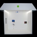
8.1.2 Prototype
CONCLUSION
The purpose of this project was to design a low-cost smart extension cord in comparison with competitive products currently available in the market. The developed product supports offline controlling as well, which is an additional feature from the existing products.Hence users get a seamless experience while operating the product. The project was able to accomplish all objectives mentioned and built a working prototype.
FUTURE SCOPE
• Can implement the concept in ‘multi-outlet wall sockets' in the residential buildings.
• New features :
◦ Gesture & Sound (Finger snapping/tapping) based offline control.
◦ Individual Outlet power management.
◦ Smart assistants like Alexa/google//Siri support.

Comments