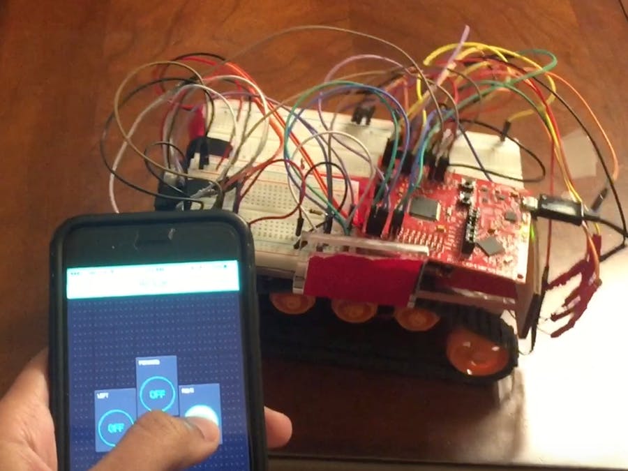
This project allows a user to control an RC wirelessly via WiFi through the use of the app, Blynk, which must be downloaded on your phone. This project is a continuation from the Line Follower Robot project I posted previously, which you can find HERE. If you have not already seen that project and you are just getting started with microcontrollers, I would recommend visiting that project first, and come here after.
Below is what that final product will look like when you're done!
NOTE: The car is connected to the laptop for power supply, but you can easily exchange this with a portable battery charger
SetupThe setup for this RC car is almost the same as the line follower robot. To an extent, it is also simpler because photoresistors and the IR sensor is not needed anymore, unless you would like to create a car that can line follow as well as be controlled with your phone. However, an additional component is also needed, the Texas Instruments CC3100 Booster Pack. This allows the microcontroller to connect to the internet and receive commands given from your phone.
Additionally, you will need to download the Blynk app on your phone and download the Blynk library on your computer, which you can find HERE. After doing so, you will need to login on the app to obtain your authentication token for the particular program you create. You will need this in your code and replace "Authentication" with your token. Make sure your token is in quotation marks.
//Obtain your Authentication Token from the Blynk app
char auth[] = "Authentication";
Next, you will need to input the WiFi name and password of which your car will be connected to. Input this information where it says WiFi name and WiFi password.
// Your WiFi credentials
char ssid[] = "WiFi Name";
char pass[] = "WiFi Password";      // Set to "" for open networks
After this, it is necessary to set up the pins for the motors and understand how to maneuver the car with the motors. Turning signal 1 HIGH and signal 2 LOW for one motor will make the motor go one direction, but if you turn signal 2 HIGH and signal 1 LOW, it will go in the opposite direction.
Turning Right: To turn right, the left motor should go forward and the right motor should either be stopped or go backwards.
Turning Left: To turn left, the right motor should go forward and the right motor should either be stopped or go backwards.
- Making one motor go forward and the other stopped will make the robot pivot about the non-moving motor.
- Making one motor go forward and the other backwards will make the robot fully rotate about the center of the robot.
Once that is complete, it is time to start working on the virtual pins set up in the Blynk application. For ease of use, I created four buttons, forward, backwards, left, and right, that the user can choose the robot to do. Below is an example of how one of the Blynk buttons are programmed. As you can see, the "V0" stands for virtual pin 0, and to program other buttons, you should open the Blynk app and drag and drop multiple buttons, and connect them to different virtual pins. To program each virtual pin, all that is needed is to change the "V0" to V1, V2, V3, etc. and edit the code on the inside. Below shows how to make one button go straight. Follow this example for the other three buttons, and you'll be done.
BLYNK_WRITE(V0)//FORWARD
{
 //Print to the terminal
 BLYNK_LOG("Got a value: %s", param.asStr());
 int i = param.asInt();
 if(i == 1)
 {
  digitalWrite(29, HIGH);
  digitalWrite(30, LOW); //LEFT MOTOR GOES FORWARD
  digitalWrite(32, HIGH);
  digitalWrite(31, LOW); //RIGHT MOTOR GOES FORWARD
 }
 else if(i == 0)
 {
  digitalWrite(29, LOW);
  digitalWrite(30, LOW); //LEFT MOTOR STOPS
  digitalWrite(32, LOW);
  digitalWrite(31, LOW); //RIGHT MOTOR STOPS
 }
}
Now that you've completed programming your car, you can control it from anywhere in the world, as long as you have internet access!


Comments
Please log in or sign up to comment.