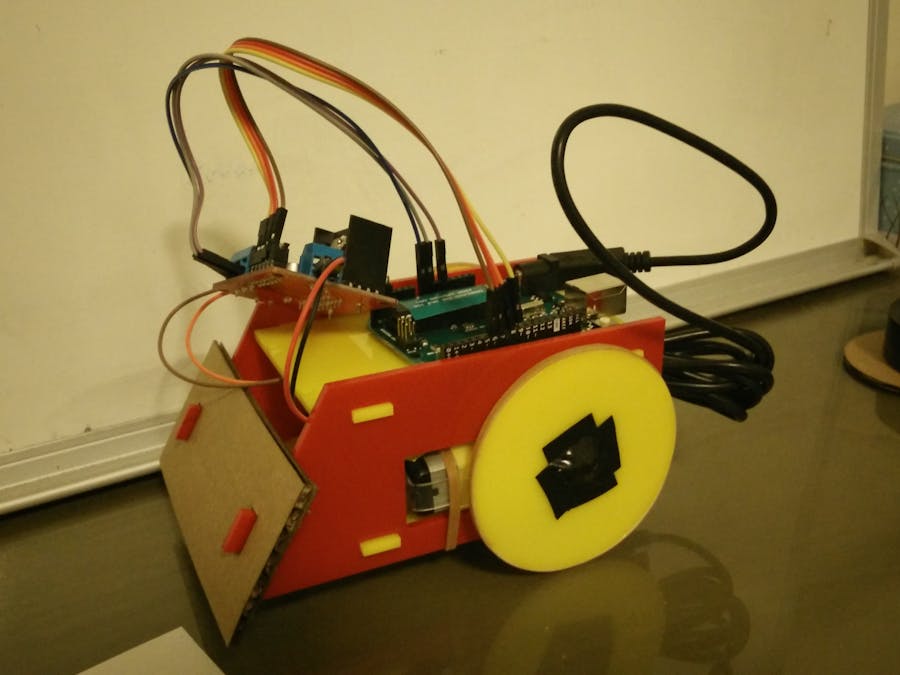
I started out with trying to research what had already been done regarding arduino remote controlled cars. I was able to find http://sumobotkit.com/, which is an open source robot kit for laser cutting originally developed for NodeBots Day. They also included templates for the vehicle and source code. I made some modifications to this version to suit my needs and budget.
First, I wanted to use two DC motors instead of two continuously rotating servos in order to save money. I altered the Adobe Illustrator files for the laser cutting as follows:
I had to measure out the holes for the DC motor, the arduino, the L298N H-bridge, and the castor on the bottom. To do this, I first printed out the template provided and remeasured it for my parts. I had to print out many versions of the cardboard before I got the measurements exactly correct for the arduino and the L298N.
I also decided to make my own caster rather than purchase one as they did in the tutorial for the sumo bot. They provided a .scad file with code to be able to modify the dimensions. In order to open the .scad file, I had to download OpenSCAD. I then got a marble from Daiso and adjusted the .scad file to be able to fit the marble and adjusted it to be the right height for the vehicle.
Then, I converted the scad file to a .stl file and loaded it into Cura to save as a gCode file (sliced for the 3D printer to read) and 3D printed it!
Results:
These were the dimensions I ended up using for the caster:
WallThickness = 2;
BallSize = 16.5;
Airgap = .5;
Mount = 3;
TotalHeight = 21.67;
MountScrewRad = 1.5; //3mm screw
BallProtrude = .33; //percentage of ball radius sticking out
//total 22mm
MountType = 1; //1=ears 2=center screw
ScrewSpacing = 25.11;
It turned out that the ball wasn't lubricated enough, so it didn't actually roll, but it was still able to act as a third leg.
I originally wanted to use zip ties to tie down the motors, but the zip ties I got were too small. In order to work around this, I cut a rubber band in half and used that to tie the DC motors in place.
Once I felt I had the measurements right, I proceeded to laser cut the shapes on acrylic plastic. I encountered a few glitches though. One learning I had was that the paper on the acrylic should be face down on the laser cutting machine or else the plastic will get damaged from not being protected by paper. I thought the top would be damaged from being close to the laser cutting head, but the bed actually caused more damage. I also learned that the cardboard was also more forgiving than the plastic. The cardboard could be stretched to fit, but the acrylic could not. Something that fit snugly using cardboard was actually too small when using the laser cut plastic. The front piece would not fit all, but unfortunately I ran out of acrylic plastic to laser cut that again.
I originally bought a battery pack that fit in the car, but then I realized that I also had a smartphone power bank that had 5V output, which could be used instead and would save me from constantly purchasing batteries.
After I resized the file to make the wheel holes large enough for the DC motor axels, I was able to put the car together. These were the steps:
1) Fixed the motors on the chassis with rubber bands
2) Used electrical tape to tape the jumper wire cables to the DC motors. The DC motor attachments were very fragile, so I had to make sure that the wires were not loose or bending the fasteners around the DC motor or else they could break off.
3) Superglued rubber bands onto the wheels to increase traction on the wheels
4) Put electrical tape over the center of the wheels to act as hubs.
5) Superglued standoffs to the top of the chassis so that the arduino and the L298N could be screwed on the top. I needed standoffs so that the bottom of the module and the arduino would not be damaged by rubbing against the plastic while moving. I paired these standoffs required M3, 1/4'' screws. I initially glued the standoffs on the wrong side of the plastic, so the arduino would not properly fit! I had to re-laser cut the piece and glue new standoffs.
6) Taped the ball and caster on the bottom of the chassis for the time being.
I then uploaded code to see if the device could get moving. This initial code hard-coded the forward, backward, and turning motions. Below is the demo:


_ztBMuBhMHo.jpg?auto=compress%2Cformat&w=48&h=48&fit=fill&bg=ffffff)


Comments
Please log in or sign up to comment.