First, I cut a strip of male header pins to the correct length, which was 10 pins. Then, I installed the Adafruit library (Software: UART Service) according to the Adafruit Tutorial.
I also installed Adafruit Bluefruit LE Connect app on my Android smartphone.
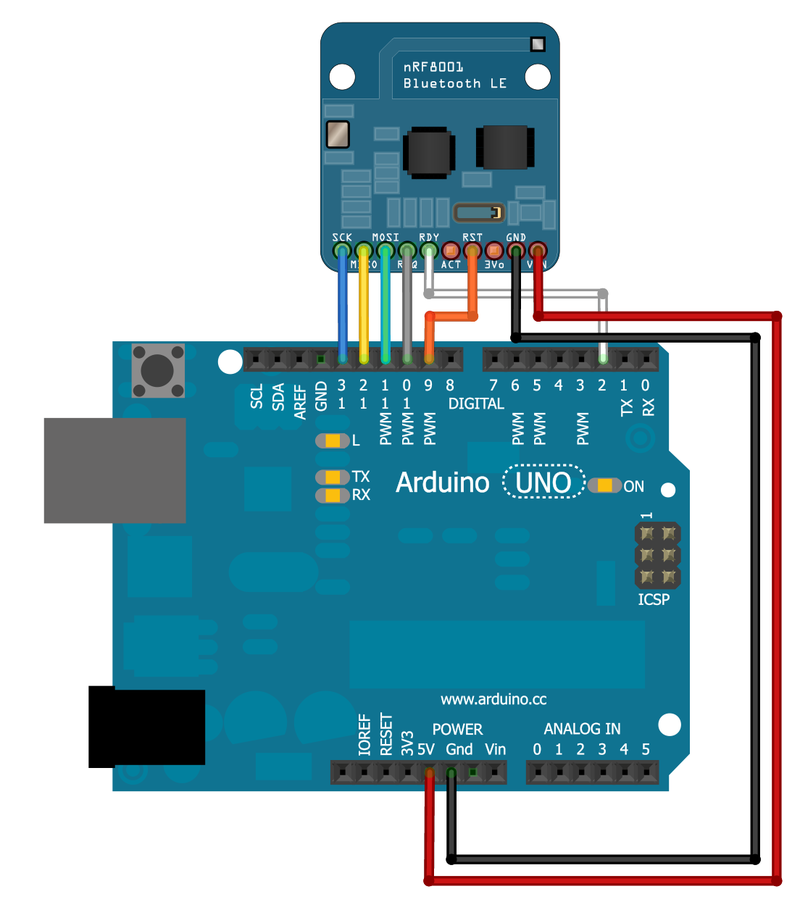
I then connected the bluetooth module nRF001 to the arduino following the instructions and schematic in the above tutorial. Everything was the same except the RST went to pin 4 instead of pin 9~ since the 9~ pin was already being used by one of the motors on my vehicle.
To run echoDemo, I used the code provided on the site and changed the pin for RST from 9 to 4. Note that you need to import the code into the Arduino Libraries folder. In order to do this on Mac, go to Finder > Applications > [Right click] Arduino > Show Package Contents. Then find the folder "libraries" by opening the Contents folder followed by the Java folder. Drag the Adafruit_nRF8001 folder into the libraries folder. There will also be the examples echoDemo and callbackDemo, which you should put into the "examples" folder, also in the Java folder. Put the two demo files into its own folder called Adafruit_nRF8001 within the "examples" folder.
When I ran the echoDemo, I received the error message, "Adafruit Bluefruit Low Energy nRF8001 Print echo demo" in the serial monitor with baud rate 11520, , which means the bluetooth module never connected. When I removed the bluetooth module, I received the same message. Interestingly, I saw the bluetooth via my phone, but was unable to connect.
Then, I tried the datamode tutorial by following the instructions on this website: https://learn.adafruit.com/introducing-the-adafruit-bluefruit-le-uart-friend?view=all In the software section, I scrolled to the "Select the Serial Bus" section. I followed the instructions for "UART Based Boards (Bluefruit LE UART Friend)", which instructs you to uncomment the Software Serial lines and to comment out the hardware SPI lines in the example. I also changed the pin for RST from 9 to 4. The code compiled, but output the error message "Couldn't find Bluefruit, make sure it's in CoMmanD mode & check wiring?"
After consulting others for help, I found out two things I was doing wrong:
- This Bluetooth module was SPI, not UART.
- The Bluetooth module needed to be soldered to the header pins in order to conduct power
After changing my code to reflect the SPI module (commenting out the UART section) and soldering the header pins, I used the echoDemo example code and was finally able to "advertise" or connect to my phone! I then used the callbackEcho demo. On my Android smartphone, I connected with the bluetooth module in "UART" mode and was able to send messages and see them display in the serial monitor console. I then chose to connect via the "controller" mode and scrolled down to the "Control Pad" option, which allowed me to use the up/down/left/and right buttons on my smartphone. By viewing the serial monitor, I found out that the there is a character number that was associated with each direction. Specifically, '5' is for forward, '6' for backward, '7' for left, and '8' for right. Therefore, I created a macro in the code to assign each character to its respective direction:
// c macro that replaces defined word when compiled
#define BUTTON_FORWARD '5'
#define BUTTON_BACK '6'
#define BUTTON_LEFT '7'
#define BUTTON_RIGHT '8'
From the callbackEcho demo code, I was able to parse the character that was returned to determine which direction was selected.
I then combined the callbackEcho demo code with my motor control logic code with the idea that the bluetooth would eventually control my motors. However, when I combined the two programs, the bluetooth was no longer advertising. The solution was to comment out the remote control line (associated with my d-pad control) in the loop(). For some reason, the uart.pollACI(); code could not run simultaneously with the remote control code.
Now the bluetooth module was advertising, but the motors were not moving. To debug, I disconnected the bluetooth module and reconnected the d-pad to make sure that was still working and there wasn't a problem with the motors. The d-pad control still worked, so there shouldn't have been an issue with the motors. I noticed that the L298N H-bridge red light on the module was much brighter when using the D-pad, because it was obtaining extra power from being connected to the breadboard. I concluded that there was probably just not enough power for the motors to move when the bluetooth was connected since it didn't have that additional power source.
After powering the H-bridge with an additional 6V from 4x AA batteries, it worked!


_ztBMuBhMHo.jpg?auto=compress%2Cformat&w=48&h=48&fit=fill&bg=ffffff)


Comments