


Hardware components | ||||||
 |
| × | 1 | |||
 |
| × | 2 | |||
 |
| × | 1 | |||
| × | 1 | ||||
| × | 1 | ||||
 |
| × | 3 | |||
 |
| × | 1 | |||
 |
| × | 1 | |||
 |
| × | 1 | |||
 |
| × | 3 | |||
Software apps and online services | ||||||
 |
| |||||
Hand tools and fabrication machines | ||||||
 |
| |||||
 |
| |||||
In today's world, technology has advanced to a point where we can control devices using just our eyes. This project aims to demonstrate how to use Hexabitz modules to control LEDs based on eye movement signals captured by an electrooculography (EOG) sensor. By integrating hardware and software, we can create a system that allows users to interact with technology in a whole new way.
This project can have practical applications in assistive technology for individuals with motor disabilities. The Hexabitz modules provide a modular and flexible platform for building and customizing the project according to specific needs. Follow along with the tutorial to learn how to build and program this eye-controlled LED project.
👁️ Electrooculography (EOG):Electrooculography (EOG) is a technique for measuring the corneo-retinal standing potential that exists between the front and the back of the human eye. The resulting signal is called EOG.
To measure eye movement, pairs of electrodes are typically placed either above and below the eye or to the left and right of the eye. If the eye moves from center position toward one of the two electrodes, this electrode "sees" the positive side of the retina and the opposite electrode "sees" the negative side of the retina. Consequently, a potential difference occurs between the electrodes. Assuming that the resting potential is constant, the recorded potential is a measure of the eye's position.
In 1951 Elwin Marg described and named electrooculogram for a technique of measuring the resting potential of the retina in the human eye.
Common electrode placement for vertical and horizontal EOG recording is shown in the image below 👀
- Right and left eye movement: horizontal electrodes.
- Up and down eye movement: vertical electrodes.
- The common electrode you can place it on the forehead or neck.
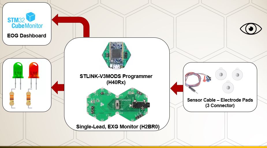
🌟 Single-Lead, EXG Monitor (H2BR0x):
Hexabitz Single-Lead, EXG Monitor Module (H2BR0) is one of a kind module that can record publication-grade biopotential signals from your body be it from the heart (ECG), brain (EEG), eyes (EOG), and muscles (EMG).
What makes it different?
- Record publication-quality biopotential signals like ECG, EMG, EOG, or EEG.
- Small size allows easy integration into mobile and space-constrained projects.
- Notch filter (second order) to remove 50 Hz AC mains.
- H2BR0 is based on STM32G0 MCU.
- Program advanced C code with our easy-to-use APIs.
- You can connect to external hardware or combine with other Hexabitz modules!
- The module is equipped with an open source MATLAB interface.
🌟 Sensor Cable – Electrode Pads (3 Connector):
This is a simple three conductor sensor cable with electrode pad leads. The cable is 24˝ long and feature a 3.5mm audio jack connector on one end with snap style receptacles for biomedical sensor pads.
🌟 STLINK-V3MODS Programmer (H40Rx):
H40Rx is a programmer module which contains STLINK-V3MODS stand-alone debugging and programming mini probe for STM32 micro-controllers (Hexabitz modules and other MCUs).
It supports the SWD (Serial Wire Debugging) interface for the communication with any STM32 micro-controller located on an application board.
It also provides bridge interfaces to several communication protocols, allowing for instance the programming of the target through boot-loader.
Step 1 : Writing codes with STM32CubeIDE software 💻
- Check out this article for writing code with STM32CubeIDE.
- Check out this article for Utilize Modules Ports as Independent Controller Ports Outside of BOS System.
- Add the instructions for configuring the pin you are going to use in gpio.c file.
GPIO_InitStruct.Pin = GPIO_PIN_3;
   GPIO_InitStruct.Mode = GPIO_MODE_OUTPUT_PP;
   GPIO_InitStruct.Pull = GPIO_NOPULL;
   GPIO_InitStruct.Speed = GPIO_SPEED_FREQ_LOW;
   HAL_GPIO_Init(GPIOD, &GPIO_InitStruct);
GPIO_InitStruct.Pin = GPIO_PIN_9;
    GPIO_InitStruct.Mode = GPIO_MODE_OUTPUT_PP;
    GPIO_InitStruct.Pull = GPIO_NOPULL;
    GPIO_InitStruct.Speed = GPIO_SPEED_FREQ_LOW;
HAL_GPIO_Init(GPIOA, &GPIO_InitStruct);- In the repeated closed loop, we made sure that MCU periodically checks the
EOGsample value andEOGfiltered sample value of the sensor using the API.
Get_EOG_Sample(&EXGStruct, &sample, &filteredSample );- If the
EOGsample value achieves the required condition, the correct led is turned on at certain time.
if(filteredSample > 1.8){
HAL_GPIO_WritePin(GPIOD,GPIO_PIN_3, 1);//p5
HAL_Delay(50);
HAL_GPIO_WritePin(GPIOD,GPIO_PIN_3, 0);}
else {
HAL_GPIO_WritePin(GPIOA,GPIO_PIN_9, 1);//p4
HAL_Delay(50);
HAL_GPIO_WritePin(GPIOA,GPIO_PIN_9, 0); }
This value was first monitored using the STM32CubeIDE debugging function to monitor sample value live expressions.
The module that captures just a quick blink of an eye.
Right blink: move to the right then to the center quickly.
Left blink: move to the left then to the center quickly.
Up blink and Down blink.
We can also examine the (eyeBlinkStatus) variable whose structure is of type enum to see which eye is moving.
typedef enum
{
NO_BLINK      = 0,
RIGHT_BLINK    = 1,
LEFT_BLINK     = 2,
}EYE_BLINK_STATUS_EUNM;
Step 2 : Set up the Monitor 📉
- Check out these articles for Build GUI using STM32CubeMonitor.
Step 3 : Hardware setup:
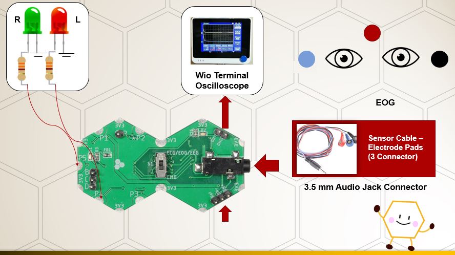
- Connect the leds to P5,P4 and GND.
- You can also solder them at the Proto module.
- You need to connect ST-Link (H40Rx Module) to ExG module by SWD (Serial Wire Debugger), and power the module in 3.3V. Learn more Here.
- The analog ExG module outputs can be checked with any oscilloscope, such as a Wio Terminal oscilloscope.
Luckily, plenty of modern microcontrollers are capable of acting as a basic oscilloscope in a pinch, provided there’s a display available to interface with it. Combined with the right software, the Wio Terminal looks like a promising option.
Examples of graph 📈
🕯️ We have used a prototype of New Year candles using cardboard, which can also be 3D printed design and equipped with LEDs. We have controlled these LEDs using EOG signals. Any suitable method can be chosen to make these candles interact with eye movement.
Happy Holidays 😃🕯️


Comments
Please log in or sign up to comment.