Materials Needed
PWM
Connect the Analog Discovery 2 to the Arduino
Adjust the signal on the screen
Best Fit
Cursor
Test our cursors
Read more- Everything from Setup (OpenScope, micro USB, wires)
- Breadboard (from Parts Kit)
- Servo (from Parts Kit)
- Arduino
- USB-B Cable
- Mini Grabbers
Connect your Servo to your Arduino using breadboard wires.
- Orange servo wire – Pin 9
- Red servo wire – Power 5V
- Black/Brown servo wire – GND
- The servo should be in SWEEP mode
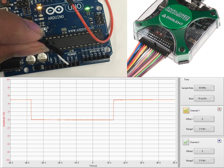
- The Arduino implements a PWM signal, that is a square wave with a duty cycle that can range from 0% to 100%.
- We will use LabForms and the Analog Discovery 2, to see exactly how long the duty cycle is on, what voltage, and duration.
- Disconnect the Servo
- Remember, the PWM Signal for the Servo is on Pin 9 of the Arduino.
- Use a breadboard wire, connect OSC1 (Orange Wire) to Pin 9.
- Close out LabForms, open up a new window (so the settings reset to default).
- Hit Run.
- Anytime you use your Oscilloscope channel, you need to have a Ground connected. In the previous exercise when we tied AWG1 to OSC1, the signal and the scope have the same ground (the Analog Discovery 2 ground). Since the Arduino is on a different circuit, the Analog Discovery 2 needs to know its ground in order to correctly measure the signal. Let’s demonstrate this.
- Plug a breadboard wire into the Analog Discovery 2 analog ground (orange or blue with white stripe) and plug it into one of the Arduino Ground Pins.
- The Arduino puts out 5V signals. We suggest “zooming out” so you have the signal cleanly on your screen.
- “Volts/” will allow you to change the Y Scale of the graph. Offset will allow you to move where 0 is.
- It’s important to make sure that the screen is “focused” on the part of the waveform with the information we need.
- For this exercise we are interested in what happens when the signal goes high, so the top of the waveform needs to be seen.
- Change your Volts/ Division to 1.00 V and Offset to 1.5 V (you can scroll or type it in). You can also type in mV instead of V.
- Cursors are a way in which you can set points of interest on a screen, and display the exact value.
- LabForms allows you to put single cursors on Time or Voltage.
- Time – We’ll use this to see if the PWM signal has a consistent duty cycle
- Voltage – We’ll use this to see what Voltage the PWM signal peaks at.
- Hit SINGLE to capture a single acquisition of the waveform
- Turn on Cursors, select Time
- Line the cursors up with the edges of the signal by moving the dotted lines at the top of the graph
- Pay attention to the calculations to the right of the cursors button
- Follow the same procedure for Voltage
14 projects • 37 followers
I work as a Product Marketing Engineer at NI. In my free time, I love tinkering and finding creative ways to solve everyday problems.


Comments
Please log in or sign up to comment.