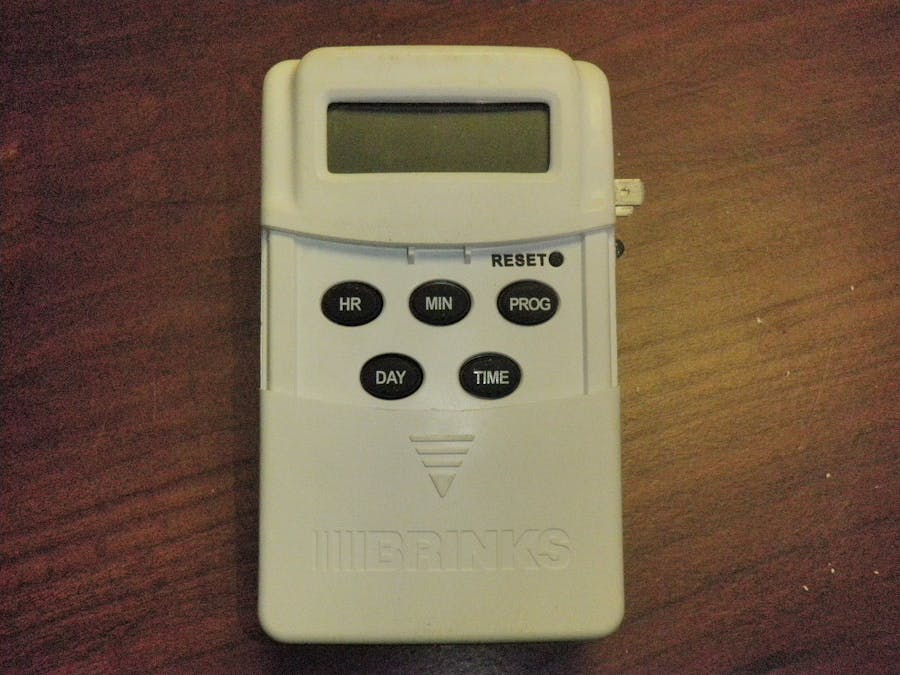
This was a digital timer made to switch AC mains that I converted to output a stable 12V 1A DC.
I bought the timer one day thinking, "I wonder how that works." It was pretty cheap, but seemed high quality.
Once I got it home, I tore it open and started poking around with a multimeter. I figured out that it had a AC/DC conversion circuit in it to drive a pretty decently specced 120VAC/12VDC relay to switch the AC on and off.
The circuit split off of the AC, dropped the 110/115V AC down to 12V DC coming out of the transformer and rectifier diodes, then down to 3.3V DC to drive the relay and timer circuit.
Long story short, I ended up removing the AC from the relay input and rerouting the 12V DC off the diodes back through the input. I threw in a 12V voltage regulator to smooth out the power and a resistor to power an LED to show when the 12V is on.
The ground wire was removed, because it was just passed through to the old output and not needed.
A heat sink was also added to the regulator so 1A can be reached without any trouble.
The blade terminals and LED fit perfectly in the old receptical output.
The buttons and screen were left stock and still work to program a 7 day timer.


Comments
Please log in or sign up to comment.