


Hardware components | ||||||
| × | 1 | ||||
| × | 1 | ||||
| × | 3 | ||||
Hand tools and fabrication machines | ||||||
 |
| |||||
FOREGROUND
I think everyone wanted a Pikachu when they were little. They were cute, fast, funny mice that stored electricity in their cheeks like a gerbil ironically.
I haven't touched pokemon since my last year of elementary, now that i've almost finished Uni and Detective pikachu has got me smiling again, I wanted to make something that I think everyone in my engineering classes could use.
I can't sell these obviously nor do I plan to. This is more something fun I wanted to try.
I got a simple pikachu plushie, you can get them for a decent £21 at a GAME store, this one comes with LED's, buttons, and a mcu with a speaker for sound effects.
This project is a simple hack.
1) Add a battery pack with charging ports to be placed on the skin
2) Mod the existing hardware for a different function
The current idea is to use the buttons for: on/off, and show the charge. The LEDs in the tail to show charge.
Initially I wanted to use the mcu to give it sound effects but that might be something i'll do later
First i'm gonna look at the pikachu circuitry.
MODDING
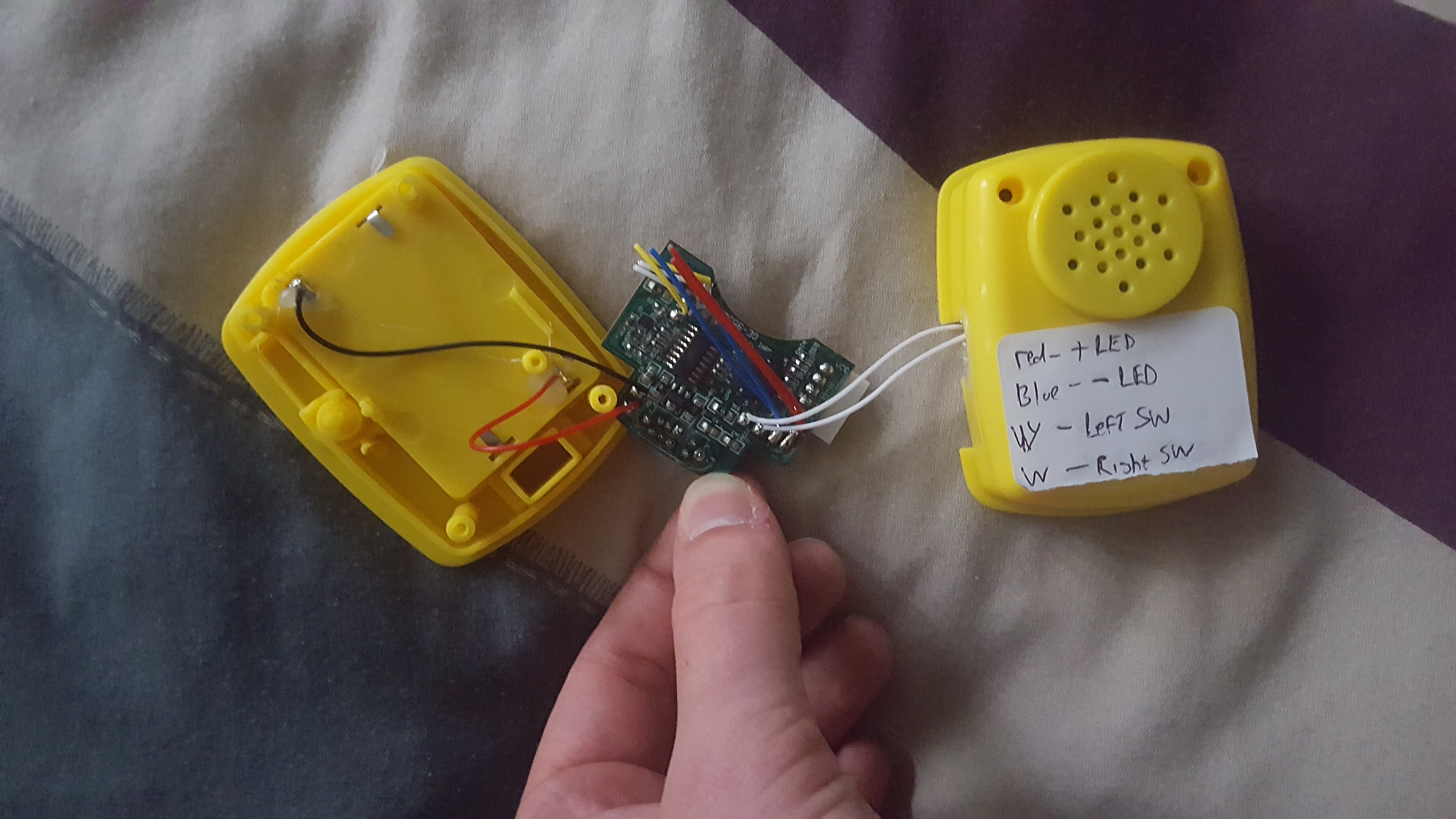
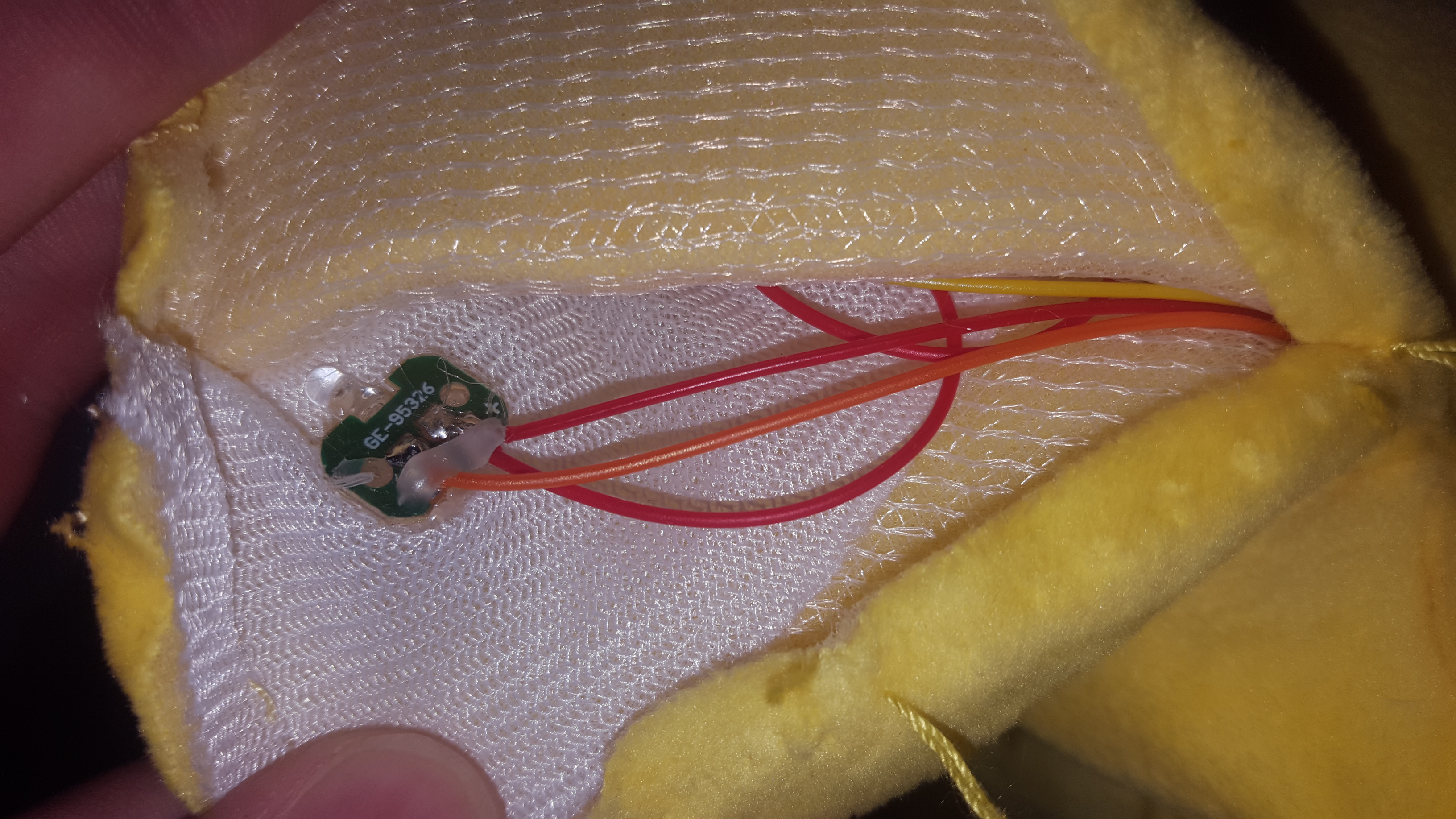
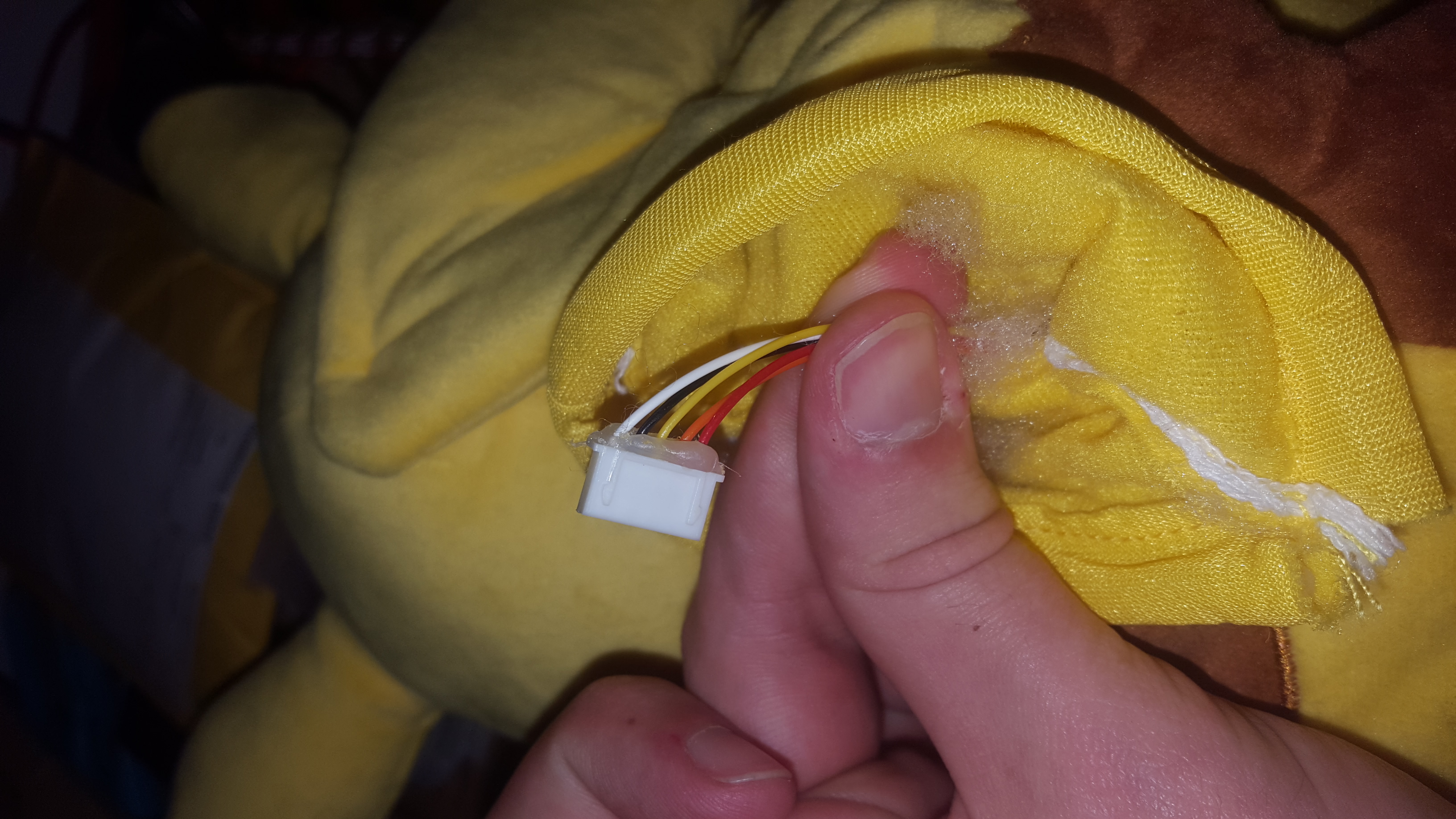
I've removed the main board, you can see it in the pictures, the codes on the chips have been removed so i'm not going to sketch the schematic and try reverse engineering the circuit but I've marked the wires. The LEDs in the tail are shown in the photos. They're all arranged in a common anode form so ground one wire to turn on LED.
Using an IC to light up the LEDs with respect to the battery voltage. Schematic attached. I initially wanted to use a LM3914 but turns out its better suited for other batteries and I just couldn't get the voltage range right so this circuit is better and will be smaller. I decided that the palm buttons will be used to see the charge.
The battery circuitry is simple but i'm not trying anything fancy and I had one of these boards laying around.
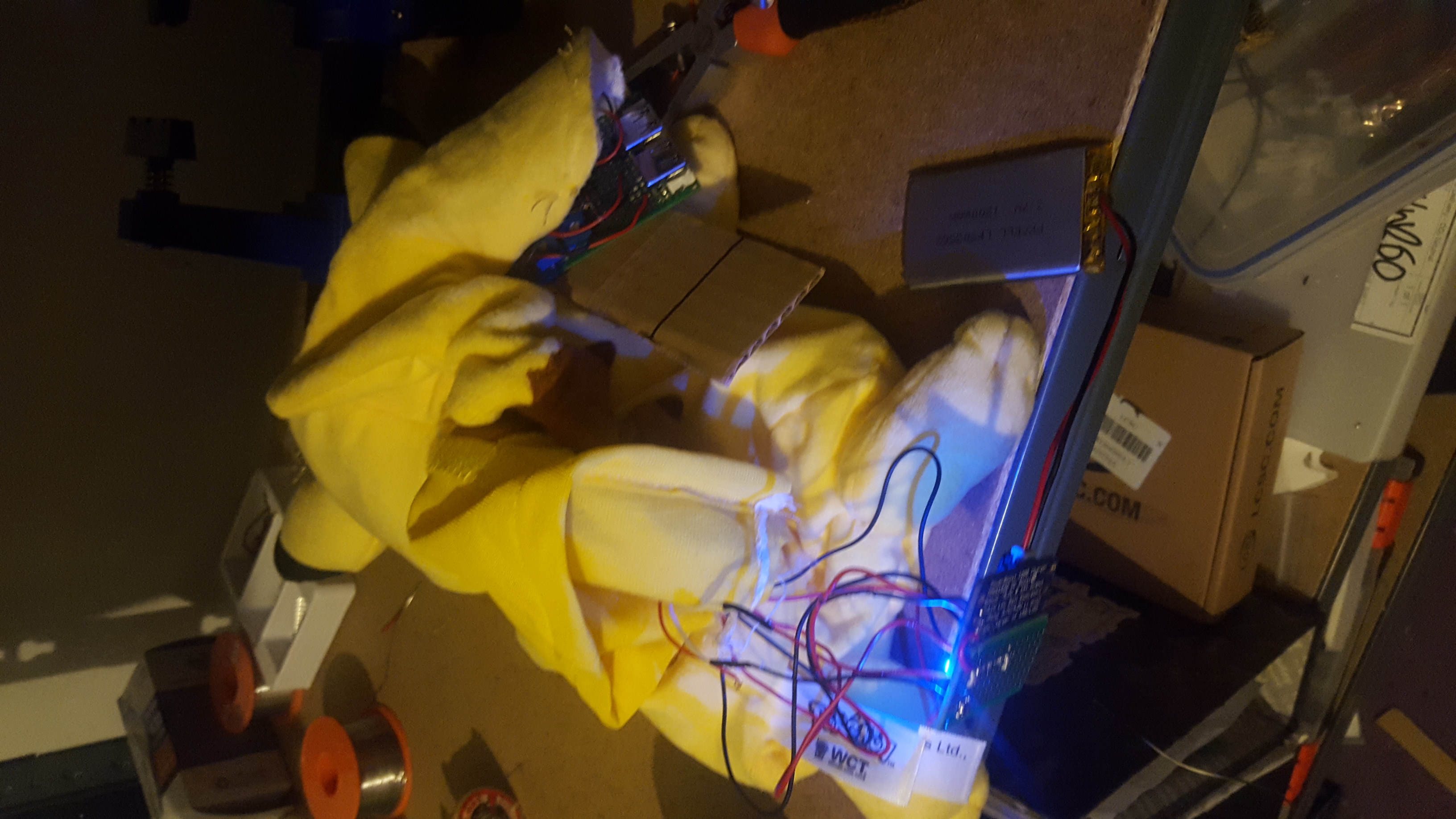
It turns out working with fabrics is harder than it looks as the soldering iron would burn through the light fabric and, on top of that, the LEDs fell out since there was nothing but hot glue. So I had to sow them in place, at least this way wiring the LEDs is easier.
I've also put together a small circuit for the batteries so they are replaceable and there's a cutoff switch.
So now the circuit is wired up and I did a small test and it works fine, the circuit is working and the buttons work as intended but the problem is the LEDS aren't glowing bright enough, so next time try a lower resistor[i used 2.2K for safety, try 470 instead]
Overall the project is working and with a bit of extra padding, it seems to be pretty nice.

Comments
Please log in or sign up to comment.