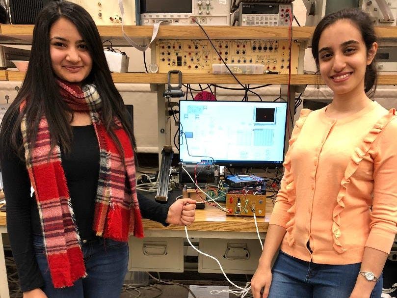
The goal of this project is to control the position of a ball on a beam that is actuated by a motor. The system is comprised of a small metal ball, a permanent magnet DC motor, a slotted beam, the MSP430, a motor amplifier, myRIO micro-controller, and a camera. We use a PD controller for the motor and beam assembly and a PID controller for the ball. Using the camera to capture the position of the ball, we can send the actual position of the ball and compare it to the desired position while also controlling the angle of the beam required to achieve that desired position of the ball on the beam. Along with that, we used the I2C protocol to send the final position of the ball to the MSP430 to turn on five LEDs each of which corresponds to a specific position on the beam to indicate the position of the ball as it moves along the beam and reach one of those positions.
System Construction:The team used MakerBeam kit to assemble the beam using L-brackets, T-slot profiled beams, and screws as shown in Figure 1. Next, the silver metal ball was painted red to make it easier for the camera to pick up its position relative to the beam. The beam was centered and mounted on the DC motor's shaft. Since the motor we used was strong and had high torque, the entire set-up was placed on a sturdy, metal plate to limit the range of the beam angle from the horizontal plane. In addition, the motor was placed on a wooden block. Therefore, the beam was positioned above the surface of the plate at an altitude of about 10 centimeters. This let the beam rotate and achieve a reasonable angle range. The motor was connected to the amplifier which acted as a power supply for the system. Along with that, myRIO microcontroller was connected to the amplifier, the motor, and the computer to act as a communicator between the LabVIEW program and the hardware components. Finally, the MSP430 micro-controller was connected to myRIO to acquire the position of the ball in order to turn on the LEDs as indicators for the ball’s position. The final assembly of the system can be seen in Figure.2, Figure.3, and Figure.4.
LabVIEW Control and Simulation Loops for the Controllers, Vision, and I2C Serial Communication:
The system was controlled using LabVIEW software, where the PID and PD controllers for the ball and the motor were implemented respectively. The program consisted of three simulation loops: one for the controllers (Figure.5), one for the vision (Figure.6), and one for the I2C protocol (Figure.7). The motor's encoder was placed in the first loop where we measured the angle of the beam. Then we used a discrete transfer function along with a gain block for the Derivative part and another gain block for the Proportional part of the PD controller to command the beam to go to a desired angle. Next, we integrated a PID controller for the ball’s position control using two discrete transfer functions and gain blocks for the Integrator as well as the Derivative parts and a gain block for the Proportional part of the PID controller.
In the second loop of the program, the camera vision was implemented in order to capture the relative position of the ball to the beam. The thresholds for the vision were calibrated using the HSV (Hue, Saturation, Value) color scale to only see the red ball along the beam. This real-time position of the ball was sent to the PID controller loop and was compared to a desired position for the ball. The output of this PID controller was sent to the motor’s PD controller loop as the desired theta. Finally, in the last loop, the I2C serial protocol for the interface between the myRIO and MSP430 was used to send the real-time position of the ball to the MSP430 micro-controller. Using Code Composer Studio software, we received that data and used it to turn on five different LEDs corresponding to five different position ranges of the ball on the beam. The LabVIEW codes have been attached to this project.
The major challenge of this project was to tune all the gains for the controllers to ensure the system functions as expected. We discovered that the proportional gain corresponds to the speed of the system response, and the integrator and the derivative gains correspond to the steady-state error and the stability of the system respectively. The ball and beam balance system is a good example of a feedback control system that demonstrates the basic functionality of PID controllers.
Videos:In the video.1, by applying external disturbance and deviating the ball from the center of the beam, it can be seen that the system is trying to position the ball in the center of the beam. There are two indicators in the front panel of LabVIEW called "row_pos" and "Desired position" which show the real-time position as well as the desired position of the ball on the beam respectively. It can be seen what the final position of the ball is after the system controls its position to place it in the desired place. By comparing the value of these two indicators, it's seen that the implemented controllers work relatively well for this system.
Video.2 shows how the LEDs turn on and off depending on the position of the ball on the beam when it moves along the beam.


Comments
Please log in or sign up to comment.