/*
* ElegooRGBled-01.ino
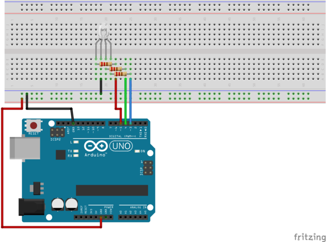
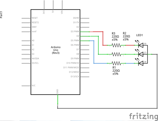
* Display discrete color spectrum using a single RGB 4-pin LED
* adapted from examples at https://www.elegoo.com/
* 2018-09-12
* armw
* v0.1
* � 2018 <reza@parkcircus.org> All Rights Reserved
*
* This program is free software; you can redistribute it and/or modify
* it under the terms of the GNU General Public License as published by
* the Free Software Foundation; either version 2 of the License, or
* (at your option) any later version.
*
* This program is distributed in the hope that it will be useful,
* but WITHOUT ANY WARRANTY; without even the implied warranty of
* MERCHANTABILITY or FITNESS FOR A PARTICULAR PURPOSE. See the
* GNU General Public License for more details.
*
* You should have received a copy of the GNU General Public License
* along with this program; if not, write to the Free Software
* Foundation, Inc., 51 Franklin Street, Fifth Floor, Boston,
* MA 02110-1301, USA.
*
* Notes
* RGB LED:
* Pin # Description
* 1 Red display
* 2 Common anode
* 3 Green display
* 4 Blue display
* Color wheel: https://en.wikipedia.org/wiki/RGB_color_model
*/
#define MAX_BITS 255 // number of bits in a byte
#define MAX_COLORS 16 // number of color codes defined in custom RGB table
#define MAX_LEDPINS 3 // number of leads in RGB LED assigned to display color
enum pins
{
red = 0,
green = 1,
blue = 2
} rgbLED;
struct ColorWheel
{
public:
byte rgb[3]; // RGB intensity values, scale 0 - 255
char* name; // command name associated with RGB triplet
};
ColorWheel colors[MAX_COLORS] =
{
{{ 0, 0, 0}, "black"}, // 0
{{128, 0, 0}, "maroon"}, // 1
{{255, 0, 0}, "red"}, // 2
{{128, 128, 0}, "olive"}, // 3
{{255, 255, 0}, "yellow"}, // 4
{{ 0, 128, 0}, "green"}, // 5
{{ 0, 255, 0}, "lime"}, // 6
{{ 0, 128, 128}, "teal"}, // 7
{{ 0, 255, 255}, "cyan"}, // 8
{{ 0, 0, 128}, "navy"}, // 9
{{ 0, 0, 255}, "blue"}, // 10
{{128, 0, 128}, "purple"}, // 11
{{255, 0, 255}, "magenta"}, // 12
{{128, 128, 128}, "gray"}, // 13
{{192, 192, 192}, "silver"}, // 14
{{255, 255, 255}, "white"} // 15
};
const int blinkPeriod = 1000; // blink interval, microseconds
const int pinsLED[MAX_LEDPINS] = {3, 4, 5}; // red, green, blue LED assignments to digital pin numbers
void pinColor(int currentIndex) // set the intensity values for the individual LED RGB pins
{
for (int p = 0; p < MAX_LEDPINS; p++) // cycle through all define pins for LED (i.e. RGB)
{
analogWrite(pinsLED[p], colors[currentIndex].rgb[p]); // set the individual LED at stated intensity
}
delay(blinkPeriod); // wait for 1,000 microseconds
return;
}
void setup() // run only once
{
int blinkSequence[] = {2, 6, 10}; // blink sequence: red=2, green=5, blue=10
for (int p = 0; p < MAX_LEDPINS; p++) // for each of the three pins in the RGB LED
{
pinMode(pinsLED[p], OUTPUT); // designate the digital pins assigned to RGB LED
pinColor(blinkSequence[p]); // setup sequence to blink R, G & B individually without diffusion
delay(blinkPeriod); // nominal waiting period
pinColor(0); // reset the LED to black display
}
delay(blinkPeriod); // wait for 1,000 microseconds
}
void fader(int pinR, int pinG, int pinB)
{
int r = 0, g = 0, b = 0; // indices for iterations through the RGB range
// sequence is ->R->G->B for 16,777,216 iterations
for (r = 0; r <= MAX_BITS; r++) // 1st parameter loop
{
analogWrite(pinsLED[pinR], r); // set the intensity of first LED specified as parameter
for (g = 0; g <= MAX_BITS; g++) // 2nd parameter loop
{
analogWrite(pinsLED[pinG], g);// set the intensity of second LED specified as parameter
for (b = 0; b <= MAX_BITS; b++) // 3rd parameter loop
{
analogWrite(pinsLED[pinB], b); // set the intensity of third LED specified as parameter
}
}
}
return;
}
void loop() // run indefinitely
{
int i = 0, j = 0, k = 0; // iteration indices
pinColor(0); // reset the LED to black display
delay(blinkPeriod); // wait for 1,000 microseconds
for (int c = 0; c < MAX_COLORS; c++) // cycle through all defined colors
{
pinColor(c); // set the LED RGB values per definition during initialization
}
delay(blinkPeriod); // pause
// color sequence is in three dimensions with sequence
// only in third dimension apparent
for (i = 0; i < MAX_LEDPINS; i++)
{
j = (i + 1) % MAX_LEDPINS;
k = (j + 1) % MAX_LEDPINS;
fader(i, j, k); // sequence is MAX_BITS * MAX_BITS * MAX_BITS for 16,777,216 iterations
}
}


Comments
Please log in or sign up to comment.