


Hardware components | ||||||
| × | 1 | ||||
| × | 1 | ||||
| × | 1 | ||||
| × | 1 | ||||
| × | 1 | ||||
| × | 1 | ||||
Software apps and online services | ||||||
 |
| |||||
This note examines the use of photo resistors, also known as Light Dependent Resistor, as an introduction to measuring light intensity. A photo resistor is often referred to as light dependent resistor owing to the fact that its resistance ranges from low to high corresponding to the intensity of the light exposed to it. When the light is high, the resistance is low. When the light is low, the resistance is high. There is a nominal lag in the response of the device from the exposure to light.
The primary applications for this sensor is in the following area but not limited to:
- Photometry:
- Light meters
- Flash control
- Street lighting control
- Home automation:
- Safety (smoke, flame and burglar) detectors
- Room lighting
- Surveillance cameras
- Automobile applications:
- Headlight dimmer
- Rear view mirror
- Obstacle detection
- Industrial:
- Position sensor
- Control
- Ambient light
- Electronic toys
- Annunciation
The resistance of the device changes inversely to light striking it. This change is proportional but non-linear. The device relies on the properties of cadmium sulfide for this phenomenon. There are regulatory statutes regarding the commercial use of this device owing to environmental concerns regarding the element cadmium. Restrictions on Hazardous Substances (RoHS) labels are applied on the packaging when applicable. The spectral response curve of cadmium sulfide is similar that of the human eye.
SpecificationThe following table summarizes the key characteristics of the device. There are many minor variations in the popular models. The reader should consult the corresponding data-sheets for more detailed information.
ParameterDescription
Peak wavelength 600 nm
Resistance at 10 lux min 1.8 K ohms, max 4.5 K ohms
Resistance at 100 lux 0.7 K ohms
Power dissipation 50 mW
LibraryThe use of the standard Arduino library call to read values from an analog pin that provides a value proportional to the resistance of the connected device.
AnalogRead
The standard function, analogRead, reads a value from an analog pin. The conversion of the analog signal to digital data is performed by the board through a 10-bit analog-to-digital converter. Owing to the latency of the operation, on the Arduino UNO board, this value cannot be read more than 10, 000 times per second since it requires approximately 100 µs to complete the operation.
The Arduino UNO board has six analog pins labeled from A0 to A5. The corresponding pin numbers for this function range from 0 to 5.
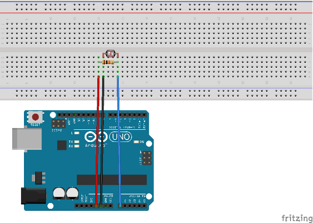
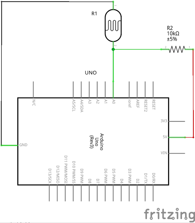
UsageThe assembly shown above will apply equally for the test cases in this elementary exercise:
- Continuous polling of data
- Interrupt driven data processing
- Within interrupt handler
- Inside the standard loop function
This method is the simplest to understand since an explicit hold is placed by invoking the standard delay function directly as shown below:
void loop()
{
  Serial.println(analogRead(pinPHOTOsensor)); // read/write directly for serial plotter
  delay(1000);              // 1,000 ms = 1 sec
}
The use of the delay function may be expedient but there some handicaps for the duration that this function is active such as:
- Other pin readings are suspended
- Pin operations are blocked
- Calculations cannot proceed
In practical terms, the activities crawl to a halt. For this reason, it may be preferable to use the intrinsic timing functions of the board to perform an operation at a regular frequency. Once an interrupt is setup, the board will invoke the corresponding service routine at the specified interval where custom operations may be performed. (The other type of interrupt will be examined in a subsequent note on other sensors where autonomous detection may be desirable). Please consult the references section for links to information on the use of interrupts and their associated handler routines.
There are two examples to illustrate the interrupt handler method:
- Reading within handler
- Reading outside handler
This method does not require any operation directly within the standard loop function. The reading (and writing) of the data is performed within the interrupt service handler routine:
void loop()
{
}
This method is primarily intended to avoid long running instructions within the interrupt handler routine. The interrupt service routine sets a flag which is examined in the loop function to perform the processing of the data from the photo-resistor.
void loop()
{
  if (interrupted)
  {
    interrupted = false;
    Serial.println(analogRead(pinPHOTOsensor)); // for use on serial line, stay tuned
  }
}
References
Photosensitive resistors series
TO-18Ceramic Package Photocell
Simple test of the functionality of the photo resistor
Luminosity sensor Photoresistor GL5528 LDR THT for Arduino


Comments
Please log in or sign up to comment.