


Hardware components | ||||||
 |
| × | 1 | |||
| × | 1 | ||||
| × | 1 | ||||
 |
| × | 1 | |||
| × | 1 | ||||
Software apps and online services | ||||||
 |
| |||||
Or do you hear me active or passively?
Introduction This note examines the simplest way to generate sound using a piezo-electric buzzer with an Arduino single board microcomputer. There are very low cost devices that use piezo-electricity with external drivers to generate a buzzing sound. The primary applications for these devices are in small electronic equipment for domestic use.
LimitationsThis note intentionally omits secondary components in the test assemblies so as to focus on introductory tests with the buzzers. Once these tests have been validated, the reader should extend the application for practical projects where the buzzer will work in conjunction with other devices and sensors.
Story The two types of buzzers used commonly with single board computers are of the types:
- passive
- active
The types differ in the use of electrical feed to drive the respective device. The physical dimensions of the cheaper devices is shown below:
The active buzzer relies on an internal oscillator circuit to synthesize the sound. The application of DC voltage to the positive terminal (with the negative terminal grounded) generates a tone. For the more simpler types of active buzzers, the tone emanating from the device is limited to a single frequency with minor tolerance variations. Since this device is triggered by the simple application of the required voltage as the HIGH state, as a corollary, it requires the subsequent call with a LOW state for the signal. The simple on/off control of the active buzzer for the sound generation is its popularity where tonal frequencies are unimportant.
While the top view of the active buzzer for a class of models may appear to be the same, the bottom view has a black vinyl cover through which the two electrodes protrude.
PassiveThe passive buzzer generates a tone with the application of a DC voltage. The frequency of this voltage controls the pitch of the sound from the device. The call parameters for the function to drive this device may optionally include the duration of the applied voltage. The external control of the tone frequency and the corresponding duration is a minor advantage of the passive buzzer.
The bottom view of the passive buzzer exposes the micro-circuit (green) board with components of the device since it does not have the black vinyl cover.
LibraryThe control of the two types of buzzers remains standard functionality for Arduino boards.
ActiveThe standard analogWrite function controls the active buzzer (assuming that the latter is connected using one of the analog pins on the board):
Function
Description
analogWrite(pin, state)
pin – the Arduino board (digital) pin that is connected to the positive terminal of the device
state – the value is LOW or HIGH for off and on respectively
PassiveThe standard set of functions (under Advanced I/O) to control the passive buzzer device are:
- tone – sends a square wave signal to the buzzer to generate the tone at the specified frequency
- noTone – terminates the generation of the tone at the buzzer
Function
Description
tone(pin, frequency)
or
tone(pin, frequency, duration)
pin – the Arduino board (digital) pin that is connected to the positive terminal of the device
frequency – the oscillation frequency of the tone, Hz
duration – the time period for the generation of the tone, milliseconds
noTone(pin)
pin – the Arduino board pin that is connected to the positive terminal of the device minute
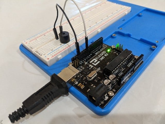
Documenting the Build All projects in this introductory set of basic and elementary projects, the microcomputer board and the breadboard are mounted on a base-plate. This technique has been illustrated in a previous project and for the sake of brevity will not be repeated here.
The final assembly is shown below:
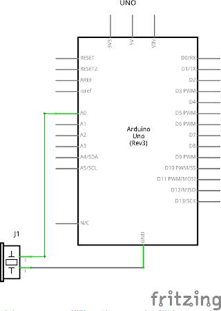
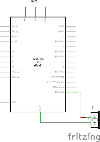
SchematicsThe diagrams below illustrate the two schematics for the elementary exercises to test the active and passive buzzers:
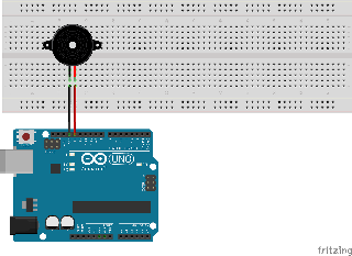
The assembly diagrams below illustrate the nominal layouts for the exercises to test the active and passive buzzers respectively:
Active buzzerWhile this exercise illustrates a direct connection to an analog pin to drive the active buzzer owing to low current consumption requirements for the device, higher performing models may benefit from external circuitry.
The simplest assembly diagram for a passive buzzer uses one of the PWM digital pins (e.g. 9 in this illustration) directly owing to the very low current consumption requirements. A PWM capable pin supports a square wave pulse which should correspond to required frequency of the tone. Owing to clock frequency of the board there is a lower limit to the operational frequency band (~20 Hz to 20 kHz). The lower limit for the Arduino UNO board is 37 Hz. Of course, the human ear cannot detect audio frequencies beyond the upper limit
See GitHubSee video
Test casesOne test for each of the two buzzers – active and passive.
ActiveThe preferred method to drive the active buzzer relies on delivering the operating voltage to an analog pin on the Arduino board as shown below:
#define pinBuzzer A0          // analog pin for active buzzer
bool beeped = false;          // iteration variable
void setup()
{
  pinMode(pinBuzzer, OUTPUT); // housekeeping
  beeped = false;             // redundant initialization
}
void beep(int pinAnalog, byte intensity, int duration)
{
  analogWrite(pinAnalog, intensity); // the lower values of intensity, < 10, may have inconsistent effect
  delay(duration);            // duration, ms
  analogWrite(pinAnalog, LOW);// turn off signal
}
void loop()
{
  if (!beeped)                  // itz bin dun?
  {
    beeped = !beeped;           // only one cycle, please!
    for (byte i = LOW + 1; i < HIGH; i++) // a nominal iteration to assess intensity on emanating tone
    {
      beep(pinBuzzer, i, i * 1000); // unleash the signal
      delay(5000);              // hold for 5 secs
    }
  }
}
The passive buzzer requires a square wave signal which is best delivered from a PWM compliant digital pin on the Arduino board as shown below:
#include "pitches.h"
#define pinBuzzer 9   // board pin reference number
struct notes {
  int note;           // using definition in pitches.h
  int duration;       // milliseconds for correponding note?
                      // 4 = quarter note, 8 = eighth note, etc.:
} melody[] =
{
  {NOTE_E7, 12},  {NOTE_E7, 12},  {0, 12},        {NOTE_E7, 12},
  {0, 12},        {NOTE_C7, 12},  {NOTE_E7, 12},  {0, 12},
  {NOTE_G7, 12},  {0,  12},       {0,  12},       {0,  12},
  {NOTE_G6, 12},  {0, 12},        {0, 12},        {0, 12},
  {NOTE_C7, 12},  {0, 12},        {0, 12},        {NOTE_G6, 12},
  {0, 12},        {0, 12},        {NOTE_E6, 12},  {0, 12},
  {0, 12},        {NOTE_A6, 12},  {0, 12},        {NOTE_B6, 12},
  {0, 12},        {NOTE_AS6, 12}, {NOTE_A6, 12},  {0, 12},
  {NOTE_G6, 9},   {NOTE_E7, 9},   {NOTE_G7, 9},
  {NOTE_A7, 12},  {0, 12},        {NOTE_F7, 12},  {NOTE_G7, 12},
  {0, 12},        {NOTE_E7, 12},  {0, 12},        {NOTE_C7, 12},
  {NOTE_D7, 12},  {NOTE_B6, 12},  {0, 12},        {0, 12},
  {NOTE_C7, 12},  {0, 12},        {0, 12},        {NOTE_G6, 12},
  {0, 12},        {0, 12},        {NOTE_E6, 12},  {0, 12},
  {0, 12},        {NOTE_A6, 12},  {0, 12},        {NOTE_B6, 12},
  {0, 12},        {NOTE_AS6, 12}, {NOTE_A6, 12},  {0, 12},
  {NOTE_G6, 9},   {NOTE_E7, 9},   {NOTE_G7, 9},
  {NOTE_A7, 12},  {0, 12},        {NOTE_F7, 12},  {NOTE_G7, 12},
  {0, 12},        {NOTE_E7, 12},  {0, 12},        {NOTE_C7, 12},
  {NOTE_D7, 12},  {NOTE_B6, 12},  {0, 12},        {0, 12}
};
bool played = false;
void setup() {
  pinMode(pinBuzzer, OUTPUT);
  played = false;
}
void loop() {
  int noteDuration = 0, pauseBetweenNotes = 0;
  if (!played)
  {
    played = !played;
                          // iterate over the notes of the melody
    for (int currentNote = 0; currentNote < sizeof(melody)/sizeof(melody[0]); currentNote++)
    {
                          // to calculate the note duration,
                          // take one second divided by the note type
                          //e.g. quarter note = 1000 / 4, eighth note = 1000/8, etc.
      noteDuration = 1000 / melody[currentNote].duration;
      tone(pinBuzzer, melody[currentNote].note, noteDuration);
                          // to distinguish the notes, set a minimum time between them.
                          // the note's duration + 30% seems to work well:
      pauseBetweenNotes = noteDuration * 1.30;
      delay(pauseBetweenNotes);
                          // stop the tone playing:
      noTone(pinBuzzer);
    }
  }
}
Test assembly for active buzzer with Arduino

Active Buzzer Schematic


Comments
Please log in or sign up to comment.