Or is one coming or going?
IntroductionThis note introduces the use of a magnetometer to establish a heading. The extensions to the solution for navigation purposes is food for thought for the maker embarking on this exercise.
A magnetometer measures the strength and direction of the local magnetic field with reference to the module’s orientation. The field is a combination of two factors – earth’s magnetic field and the secondary fields emanating from objects in the vicinity. The Honeywell 3-Axis module, HMC5883L, has reasonable digital compass accuracy (±2° heading) for general purpose commercial and industrial applications. The module’s popularity led Honeywell to license its manufacturing to other companies world-wide. This move resulted in cheaper variations but at the expense of minor deviations in technical standards that will be discussed in a later section of this note. This module serves the purpose of compass readings from a stationary device.
The surface stamp on the clone module, QMC5883L, is different as shown below:
Practical navigation requires an integrated accelerometer (for tilt compensation of the digital compass). This requirement opened the market for Bosch to offer a family of such products while Honeywell seems to have other fish to fry. Such a device offers 6-axis readings from the sensors on the PCB. However for the limited purposes of a “Hello World” article, this note will confine the examples to introductory evaluation of the HMC5883L module mounted on a printed circuit board (PCB) with supporting circuitry for the digital compass solution.
GyroscopeThe extension of the concept even further by adding a gyroscope sensor to the PCB (9-axis readings) serves the demands of hobbyist drones.
Printed Circuit BoardThe modules are mounted on a printed circuit board with supporting components (e.g. pull-up resistors and voltage levelers) to facilitate interface to applications. An example of this assembled components including the compass module on a PCB is shown below:
It is important to note that the ensuing part number references the magneto-resistive module but the interface is subject to the assembly design by the downstream manufacturer. The figure below illustrates the GY-271 PCB with the digital compass module surface mounted on the board. The marking on the module is “DA 5883 8014” which implies that the module is QMC5883L (and not HMC5883L). The HMC5883L module has a label "L883"on its top surface. The QMC5883L part, as shown below, has the second line marking as “5883." The address registers for the two are set differently. One of the I2C scanner utilities (in the References section) can determine the setting or the sample code by DFRobot may be used to cover both parts (as detected during object instantiation).
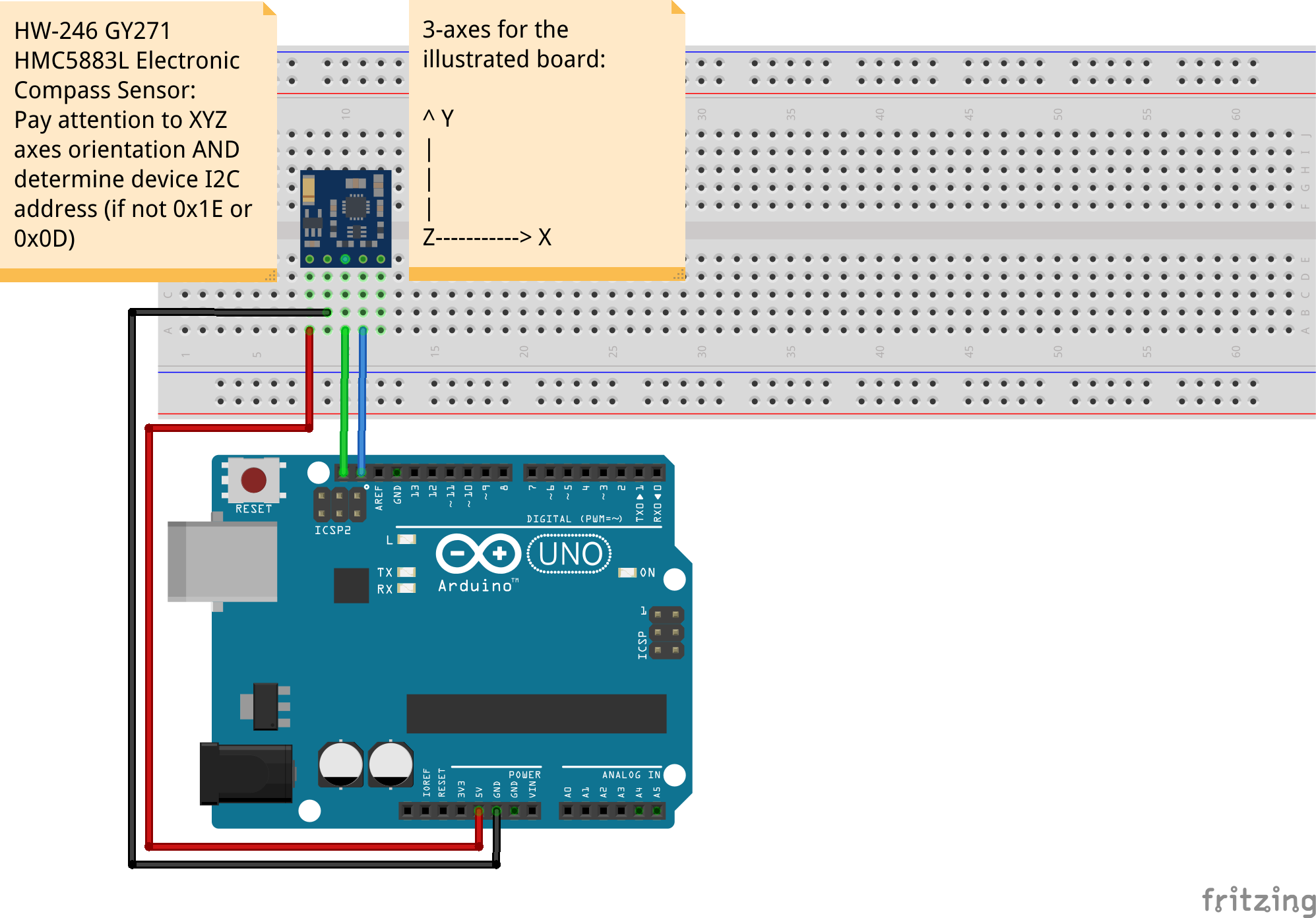
Three axesThe PCB has an etching of the 3 coordinate axes on the upper edge on the component side to assist with nominal alignment. As shown in the PCB image above, the X-Y plane is parallel to this particular board while the Z axis is perpendicular to the board. This nomenclature should be understood when interpreting the sensor readings for a given alignment. Other boards using an equivalent module may not use the same orientation for the axes.
While keeping the PCB in a horizontal (X-Y) plane (with additional leveling aids) may work for short exercises, any involuntary movement is likely to introduce tilting in the event of which the readings will have to be transformed for any practical use.
Magnetic declinationThere are very few places on Earth where the magnetic north (derived from compass readings) is aligned to the geographic true north. Magnetic declination is the difference between the values for the magnetic north and the geographic north for a geographic location. For the limited purposes of this note, daily variations in the field strengths owing to ionospheric interactions have no significant impact on the magnetic declination (e.g. < ±0.05° heading).
The magnetic north and south are drifting slowly over time. Therefore, to obtain a true measure of direction, the compass heading must be adjusted for the local magnetic declination to derive the true (geographic) north heading. Fortunately, there are authoritative sources for the relevant transformation data on magnetic declination throughout the world. The References section lists one of these sources.
Operating principleThe module’s sensor converts ambient magnetic field into electrical signals using patented thin-film alloy compositions. Supporting circuitry on the PCB transforms this output into 3-axis vector values. The assembled board relies on the popular I2C bus for input/output data exchange in accordance with the module manufacturer’s (viz. Honeywell) guidance for support circuitry as detailed in original application notes. One should determine the I2C address for these parts as early as practical. Of course, only one sensor can be used on the I2C bus.
CalculationsThe magnetic data from the electronic compass require the following set of transformations to derive the true north heading:
- Hard-iron owing to presence of ambient magnetic fields
- Soft-iron owing to presence of ferromagnetic materials
- Deviation
- Declination
- Tilt data
- Compensating factors
- Correction factors
Applications
Practical applications for the standalone and integrated sensors are tabulated below:
Stand alone magnetometer
Integrated magnetometer & accelerometer
Simple mobile technology
Motion tracking
Automation for constant heading
Fitness measurement
Magnetic field measurements
Navigation coordination
Magnetic surveys for archaeology and geology
Gaming
Healthcare monitoring
Virtual reality
Preventive maintenance
Pointing devices
Features
The electronic compass module (either HMC5883L or QMC5883L, for example) are surface mounted on a board with supporting circuitry for direct pin connection to the Arduino - pull-up resistors not needed and voltage upper limit accommodated with a matching board. The part numbers for these boards vary (e.g. GY-271, GY-273) based on interface characteristics and axes orientation.
Specifications
The key specifications of the GY-271 board are:
ParameterDescription
Sensor type Anisotropic Magnetoresistive, HMC5883L or QMC5883L
Axes 3
Interface I2C, 2-wire
Data 8-bit
Range 3 mGa – 8 Ga
Power supply 3.3 – 5 V DC for board, sensor module uses 3 V DC
Current 100 µA
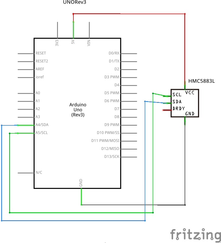
Pin connectionsThe pin connections for the GY-271 board are:
Pin numberDescription
1 VCC, 3 – 5 V DC
2 GND
3 SCL, analog, A5
4 SDA, analog, A4
6 DRDY, unused for current test exercise
For UNO Rev3 boards, the pin diagram (see References) should be consulted for alternate options for the SCL/SDA pins. In fact, the breadboard diagram in this note uses the alternate options (instead of the regular analog pins 4 and 5).
Operations
The simplest test exercise has the following steps:
- Note the address register for the compass module as shown in the table below:
ModuleRegister address
HMC5883L 0x1E
QMC5883L 0x0D
- Setup
- Loop
- Use the standard Arduino sketch hierarchy to configure the settings and read the data:
- value used: 0b00000000
- value used: 0b00010000
- value used: 0b00001100
- value used: 0b00000001
- Over Sample Ratio (OSR), Hz
- Full Scale Range (RNG), Ga
- Output Data Rate (ODR), Hz
- Measure continuously (MODE)
- Initialize the communications with the board using the register address corresponding to the board:
- Write to control register 1 for device address 0x1D (if using QMC5883L)
- Write to control register 1 at 0x09 to set:
- Update the mode register at address location 0x02
The table below illustrates the mapping for control register 1. Refer to the parenthetical abbreviations in the above list for the acronym descriptions:
Address
0x09 OSR RNG ODR MODE
LoopThe loop processing consists of the following operations performed indefinitely:
- Map data for three axes using 2 bytes per axis using the table below for guidance
- Data for each axis is 16 bits (signed integer) with values between -32768 and 32767 inclusive
- Read 6 bytes of data from 0x00 to 0x05
- If status register 0x06 is “ready” (i.e. ==1)
Address
0x00 X axis value, Least significant byte
0x01 X axis value, Most significant byte, highest bit is the sign bit
0x02 Y axis value, Least significant byte
0x03 Y axis value, Most significant byte, highest bit is the sign bit
0x04 Z axis value, Least significant byte
0x05 Z axis value, Most significant byte, highest bit is the sign bit
The datasheet has full details on the register addresses and the corresponding functions.
Bill of MaterialsPartDescriptionQuantity
UNO Arduino UNO 1
Compass GY-271 QMC5883L 3-Axis Magnetometer breakout board 1
Wires DuPont connection wires, assorted 4
BB Breadboard, optional 1
BP Baseplate, optional 1
The GY-271 board does not with soldered pins. There are two sets (one straight through, the other has a 90° bend) of pins in some of the common packages. Since it is preferable to keep the board oriented as indicated with axes annotation on the board, one should choose the right pin for the soldering task that is essentially a prerequisite for the assembly.
The output of heading data from the test exercise tracked closely to the compass readings from a smartphone app using a nominal arrangement shown below. The rotation of the baseplate had similar effects on the sensor’s output as well as the smartphone app. only.
The output displayed in the serial plotter window for a representative run is shown below. There are three line charts representing the magnetic vectors for each coordinate axis independently:
- X-axis, blue
- Y-axis, red
- Z-axis, green
The heading data from a another run is shown below:
Again, there are many diverse examples of calibrating the basic electronic compass readings on a standalone basis. I have avoided introducing these techniques in this note so that the beginner is not distracted by the computational techniques and can acquire the knowledge through self-study.
The Next StepsThis note has illustrated the simplest “Hello World” exercise for a digital compass. There are two routes for the next steps:
- Use the readings to perform more rigorous magnetometer calculations to calibrate the sensor including perhaps calibration
- Extend the functionality by seeking enhanced boards with other integrated sensors for a more advanced solution by adding these sensors incrementally:
- Accelerometer
- Gyroscope
- Global Positioning System (GPS)
There is considerable literature on electronic compass and its extensions for practical purposes. Please consult these documents for more authoritative information. This note is a very simple exercise for self-study purposes.
ReferencesApplications Manual for Portable Magnetometers
Sensing Earth’s magnetic field
Video demonstration


Comments
Please log in or sign up to comment.