

Hardware components | ||||||
 |
| × | 1 | |||
 |
| × | 1 | |||
 |
| × | 1 | |||
| × | 1 | ||||
| × | 1 | ||||
| × | 1 | ||||
| × | 1 | ||||
| × | 1 | ||||
| × | 1 | ||||
Software apps and online services | ||||||
| ||||||
Hand tools and fabrication machines | ||||||
| ||||||
| ||||||
| ||||||
| ||||||
 |
| |||||
This tutorial will help you to make your own “Hole in the Wall” game. The aim of the game is to navigate a blue LED through the holes in the walls. With each success the walls’ speed will increase, so be careful! To create the game you only need the Touch Board, a NeoPixel shield from Adafruit, some headers and a bit of soldering. If you want to add sound effects to the game, it requires some more skills, but we’ll guide you through each step. In the end, you will have an addictive game and you are free to modify it!
Materials: To begin you will need:
1x Touch Board
-
1x Adafruit NeoPixel shield
1x USB A to Micro B cable
1x 10 pin female and male pin header
2x 8 pin female and male pin headers
1x 6 pin female and male pin header
soldering equipment
-
(optional)
Electric Paint
paper
crocodile clips
scalpel
hook-up wire
multimeter
speakers or headphones
Step 1: Setting up the Touch Board
To setup the Touch Board for this project, download the project into your Arduino IDE by following Step 1 to Step 4 of the following tutorial:
Setting up Arduino with your Touch Board
Links
Step 2: Soldering the Touch Board and NeoPixel shield
In order to plug the NeoPixel shield onto the Touch Board, you need to solder the male headers onto the NeoPixel shield and the female headers onto the Touch Board. If you haven’t soldered headers before, read the articles from Sparkfun here:
How to solder – Through-hole Soldering
Arduino Shields: Installing Headers (Preparation)
Make sure to use the right male and female headers with respect to the holes on the Board and shield. On the right, you can find some guidance on which header needs to be placed where on the Board or shield. The numbers in the image indicate the number of pins of the respective header.
Links
Step 3: Soldering Success
If you have soldered the headers successfully you will have a similar result as shown on the right. Excellent!
Links
Step 4: Plugging the NeoPixel shield onto the Touch Board
When you are sure that the headers have been soldered on correctly, you can plug the NeoPixel shield into the Touch Board. Now it’s time for the code!
Links
Step 5: Load the code
Once you have connected the Touch Board to the computer, turn the board back on.
Open the Arduino IDE and load the sketch under File→Sketchbook→Touch Board Examples→hole_in_the_wall. Next, select the following:
“Bare Conductive Touch Board” under Tools→Board
“Bare Conductive Touch Board” under Tools→Port
Finally, hit Upload!
Links
Step 6: Playing the game
If everything is working correctly then a blue LED should light up in the corner. The game is working! To start the game touch electrode E5. The electrodes have following functions:
E4 – Move right
E5 – Start / reset the game
E6 – Move left
E10 – Increase brightness
E11 – Decrease brightness
The aim of the game is for the blue LED to move through the holes in the walls. The speed of the walls increases after each success until level 7. Your score is displayed on the shield once you lose. The game wraps around, so if you move beyond the left edge, you reappear on the right, and vice versa. Touch electrode 10 and 11 to increase or decrease the brightness of the LEDs. You can play the game now by just touching the electrodes, but chances are that you are going to accidentally press E5, resetting the game. Time to make a controller!
Links
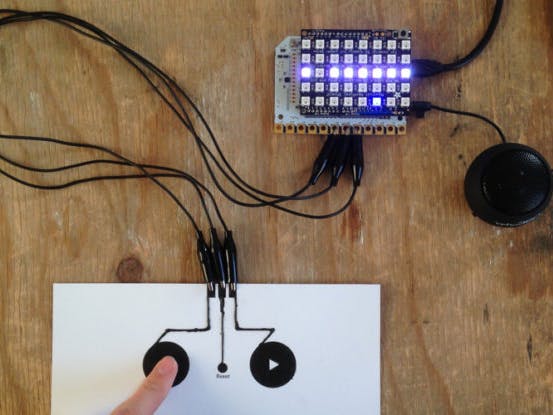
Step 7: Creating a game controller
You can connect anything conductive to the electrodes and use it as buttons. We’d love to see what you use as buttons for the game, so send us pictures of your creation on Instagram or Twitter.
Alternatively, you could draw your game controller with Electric Paint. If you want to create a controller that looks like the one on the right, you can download a template here:
Trace the outline of the game controller and fill the inside of the buttons with Electric Paint. Now we need to connect the Touch Board to our paper controller!
Links
Step 8: Connecting the Touch Board
To connect the Touch Board to the game controller, you need to create a connection between the electrodes and the painted controller. We recommend two ways to connect the Touch Board: Either to cold solder or to use crocodile clips. If you prefer to use crocodile clips, skip to the next step. If you want to cold solder, but have never done it before, have a look here:
Attaching your Touch Board – Cold Solder
First, turn the board off and place E4, E5 and E6 so that they lie above the connections of the controller. The soldering of the header is protruding below the Touch Board, so you can’t place it flat on the surface anymore. This makes it a bit unstable when moving around. We recommend to use some tape and stick it beneath the Touch Board to stabilise it.
When you’re ready, squeeze a generous amount of paint onto E4, E5 and E6 to build a good connection. Be careful that the paint doesn’t smudge and cross-connects the electrodes. After 15 minutes, once the paint has dried, turn the board back on again and give the new gaming device a go! The buttons of the controller are now working as an interface to the game.
Links
Step 9: Connecting the Board with crocodile clips
Alternatively, you can use crocodile clips instead of cold soldering the controller. When you use crocodile clips, simply cut the paper so that the electrodes of the controller are on the edge of the cut-out. Turn the board off, then connect each electrode of the controller with the respective electrode of the Board. If you have connected everything correctly, turn the board back on. That’s it! The buttons of the controller are now working as an interface to the game.
The crocodile clips can interfere with each other when the cables overlap, so make sure that the cables are spread apart.
Links
Step 10: Enabling sound effects
At this point, you have created a wholly functioning game, including a paper controller. If you want to you can now continue with this tutorial and add sound effects to it, it’s a bit more complex and requires more soldering experience, but no worries, we’ll guide you!
First, you need to separate the connection between Din and D6 on the NeoPixel shield, by cutting the trace between Din and D6 with a sharp knife. If you have never cut traces before, don’t worry: Simply pass the knife through the trace a couple of times until the connection is disrupted.
Links
Step 11: Rewire pin Din
Once you have cut the trace, you need to rewire Din with pin 11. If you are using a hook-up wire you need to strip the wire first, if you have never done that before, have a look here:
Then, take one end of the wire, bend it into a small hook and loop it around pin 11. The other end is fed through pin Din. Now you need to carefully solder the wire to each pin. The soldering of pin Din is very similar to soldering the headers as you have done in Step 2. For soldering pin 11, approach the wire with solder and iron in the angle as shown in the image on the right.
Links
Step 12: Troubleshooting
Now is a good time to check that nothing went wrong. Using a multimeter, check for continuity between pin 11 and Din. Also, check that there is no continuity between D6 and Din.
Links
Step 13: Loading the files on the SD card
If everything is working, we need to load the sound effects onto the SD card of the Touch Board. If you haven’t changed the MP3s files for the Touch Board before, have a look here:
Changing the MP3s on the Micro SD Card
The sound files we used are available here. Download the zip file and extract it. Then copy the three MP3 files, using the same naming structure, onto the SD card. Slot the SD card back into the Touch Board and open the code in the Arduino IDE. In line 47, uncomment “#define enable_audio” by removing the “//”. Then in line 63, change “#define PIN 6” to “#define PIN 11”. That’s it!
Links
Step 14: Connect the speakers
Upload the code onto the Touch Board. The final step is to connect speakers to the Touch Board. You can either use headphones or some speakers.
If you now move the blue LED, you should hear a jumping sound! You will also hear a sound when you succeed or fail to get through the hole. You can decrease the volume with E1 and increase it with E0.
Links
Step 15: I want other sounds!
If you want you can change the sound effects. We used Freesound as a source, but you can use any sound that you want. Make sure that the sound file is MP3 and that it isn’t too long, our sound files are less than a second long. We also found that to achieve the best result, the sound files need to be converted to Mono at a sample rate of 44100 Hz with a bitrate of 128 kbps. We used the program Audacity to perform any conversion, which is open source, so feel free to use it too!
If you want to convert a sound file to MP3 with Audacity, then first open the sound file with Audacity and click Tracks→”Stereo Track to Mono” to convert the file to Mono. If that option is grayed out it means that it is already in Mono. Then click File→Export Audio. In the new window, make sure the File Type is set to “MP3 Files”. Choose “Average” for the Format Options and “128 kbps” for Quality and “Joint Stereo” for Channel Mode. Hit Save and then OK. The file is now converted and can be copied onto the SD card. Make sure to name the MP3 file correctly. We used TRACK000 for the player, TRACK001 for success and TRACK002 for failure.
Links
Step 16: Explore the code
At this point: Congratulations! You have achieved a lot: You have built a fully functioning game plus successfully applied your engineering skills!
Now that the game is running, you can use your creativity to modify it: You could use a different colour for the player by changing the colour to red in the function “drawUser()” or modify the difficulty of the game by changing the value of “intervalFrameMS”, such that the walls are falling faster. You could modify the game even further, all you need to do is explore the code.
If you create your own game with our Touch Board we would love to hear from you! Send us your images or videos on Instagram or Twitter or email us at info@bareconductive.com. We’re looking forward to playing your games!


Comments