In the Arduino world, there are many projects showing how to control a robot arm or a robot car. Most of these projects are with a direct connected controller with a cable or Bluetooth dongle. Examples are XBOX or WII game controllers. There also is a generation of projects that are controlled through the internet. The Arduino runs a full webserver and can be controlled from a website or app.
I want to do this a little bit different; both the controller and the robot are build on an Arduino, and communication should be over WiFi. As they need to understand each other, an agreed protocol is needed. And I don’t want to limit myself to controlling a robot, I also want to be able to control for example a Hue light or read sensor values. Maybe also in combination with a Raspberry Pi or other platforms. (something about raising the bar high…)
I’ve reviewed many websites about (industrial) communication protocols. Although there is a lot of choices on protocols, not many of them are based on TCP or internet standards. There were 2 options (Modbus TCP and BACnet), but over all the years these exist, they are not completed for use on Arduino. Mainly because for Modbus a realtime master is difficult to setup and thus only a slave library (Mudbus) is available. And for BACnet there are only shields made to connect the Arduino, where I want to do this without shields!
So something new is needed… Lets find an Arduino based controller to work this out for.
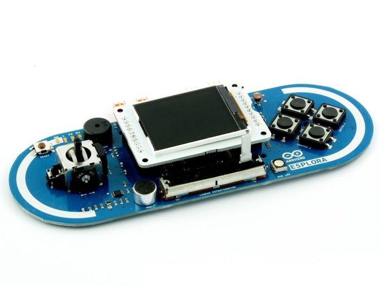
Remote Controller: Arduino EsploraThat Remote Controller is an Arduino Esplora with a 1.8” TFT screen.
But the Esplora is based on the 2013 Arduino Leonardo board without Wifi, and it lacks the pins for connecting shields. Especially when the headers are used for the TFT screen.
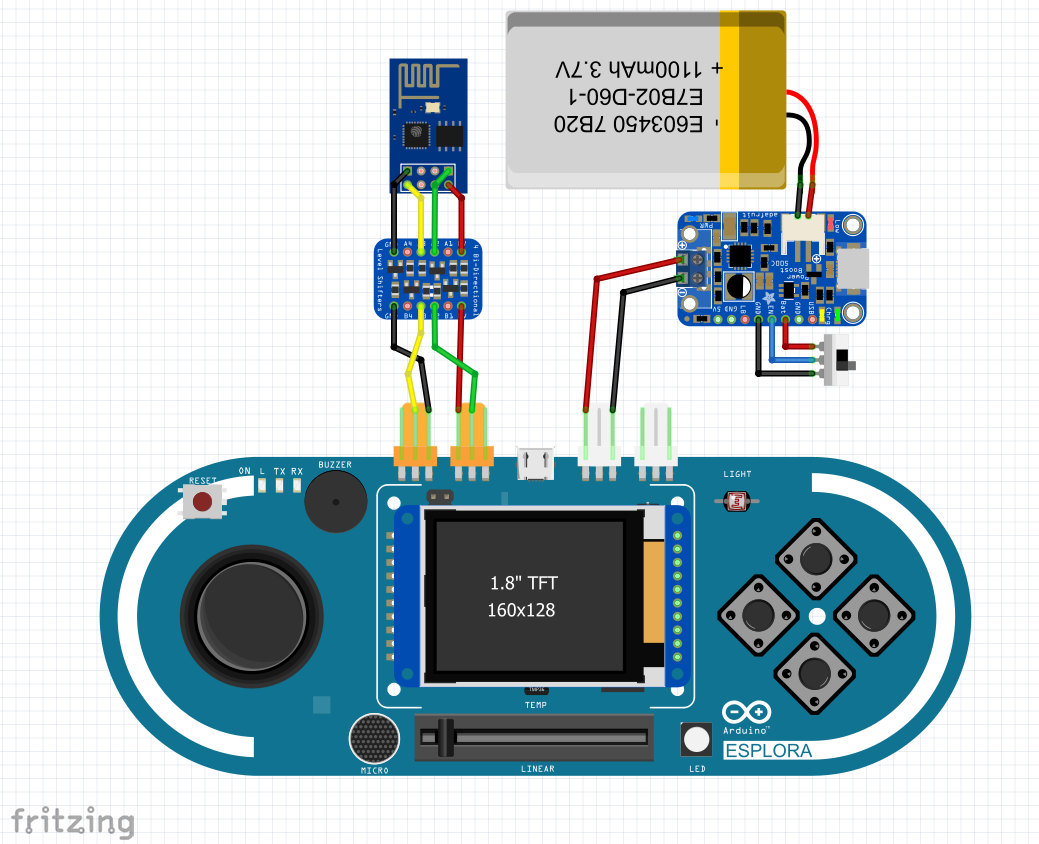
No worries, I’ve got you covered! There are 2 TinkerKit output pins on the top, and that is exactly what is needed for connecting an ESP8266 board to do TX and RX for WiFi connection over AT commands. (thanks Mike Barela for the idea of using these!)
One problem left, is that the ESP8266 is 3.3v, and the Esplora is 5v. So I’ve used the ESP8266 12-E board, that contains level shifting logic back from 5v to 3.3v.
Actually, there is one more problem left… The ESP8266 communicates by default at a baud rate of 115000. The Esplora can talk at that speed, but cannot listen at a higher speed then 9600 baud without messing the data up. Luckily, the ESP board comes with an AT command to turn down the baud rate until next power cycle or reset. I'm using that to switch to 9600 baud, but also had to change the WiFiEsp library as that does an automatic reset after initialisation.
The Esplora is not made to run with a battery. It only has a 5v micro USB socket for input. But hey, there are the TinkerKit pins again! If you just supply 5v to these pins, it works perfect. But make very sure you have the polarity correct as there is no protection by connecting this way! I took an Adafruit PowerBoost 1000c to use for the LiPo battery and taking care of charging it. Added a switch to be able to turn the power on/off.
Robot controller: Arduino MKR WIFI 1010Latest released Arduino board with an onboard WiFi chip is the MKR WIFI 1010.
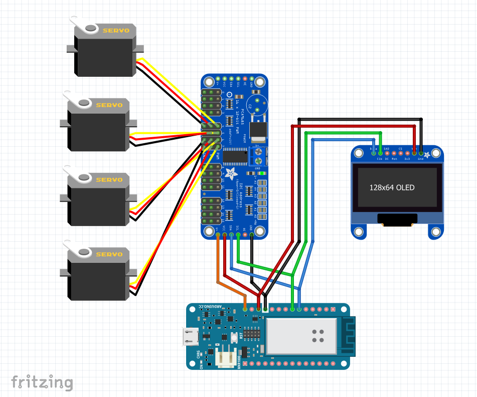
Hardware part is completed with an Adafruit PWM/Servo board, an 1.3”OLED display and a MeArm that is controlled by 4 servo motors.
The MKR series of boards is 3.3v instead of the 5.5v in older iterations of Arduino boards. The PWM/Servo board can handle both 3.3v and 5v so we are good to go. To power the servo’s, we still need 5v. I used the 5v pin on the MKR to the V+ at the PW/Servo board, but while being connected to USB of my computer the board started rebooting and I lost USB connection. Probably because I didn't use the high power USB port, or the MKR is limiting output. I have to check the real reason. Solutions I can think of: use the high power USB ports, or power the servo’s with an external adapter (I took the last option at the moment).
Robot arm: MeArmMeet the MeArm; designed by Benjamin Gray, with open source laser cut templates. I’ve ordered mine in 2015 just after the Kickstarter was funded successful and send out. Since then there were some more iterations of the MeArm featuring easier construction, you can buy the official MeArm here. They are now sold all over the world at cheap websites, and only some do proper attribution back to Benjamin.
The MeArm has 4 servo motors: Base, Elbow, Shoulder and Gripper. While playing with it, I burned some of the cheap plastic motors and put it aside. To get it working, I now changed some of the motors by metal gear motors.
To move the arm around, you can just change the PWM signal to the servo. But for the arm, I want to send coordinates. This is also known as Inverse Kinematics (IK), and there exists a terrific library for that (thanks Bob Stone!)
As the arm moves around a base, you could also use the Cylinder version of this.
Maybe you recognize the robot arm? Simone Giertz' "Toothbrush machine" is what made her famous as "Queen of Shitty Robots"!
The communication protocolFor setting up communication on a WiFi network, there are 2 main choices: TCP and UPD. What it comes down to is reliability (TCP) vs speed (UDP). Difference between TCP and UPD are very well described at this page.
Then why use UDP as it's not reliable? As UPD has less overhead, it’s better suitable for fast message delivery. Translating that to this project, to still let our source know that the message was received OK at the target, there will be send back an ACK to the source. And yes of course that ACK can go wrong too. To avoid this blocks our stream of messages, if the ACK did not come in after an interval of 30, we assume it lost. And then what… send the message again? Or just continue? I chose the last option, as it might be that the target received well, but the ACK did go wrong. But we need some safeguards to be build in.
Esplora sensors and outputThe Esplora has a range of onboard sensors and output options. That is why this is such a great board. No need to search for components and after soldering together, ending up with something bulky. The Esplora is just 1 easy board and library.
As the library will be build around the Esplora, I took this as the base for the protocol.
SENSORS:
- Pushbuttons (S1,S2,S3,S4)
- Joystick (JX,JY)
- Joystick push (S5)
- Slider (SL)
- Light (LU)
- Microphone (MI)
- Accellerator (AX,AY,AZ)
- Thermometer (TC)
OUTPUT:
- RGB (LR,LG,LB)
- Spreaker (SP)
- Screen (needs an advanced message)
The robot is always in WiFi Access Point (AP) mode. The Esplora Controller is in WiFi Device mode and scans for networks. Selected network SSID is reversed as password and connection is made. Once connection is created, request for identification is send as a WEB protocol. If this is indeed a robot that has this protocol logic, a welcome message is returned (HTML of XML page) that identifies the robot and says what the robot wants to receive (see list of sensors). SD card on Esplora has pre-configured set of images to show once robot is selected.
At the controller, a loop runs with time interval of 10 to send out sensor data. It then waits for ACK message (takes 2) and at 10 sends anew message. If no ACK is received, after waiting 30 it assumes the message was lost and continues with a new command. Command only contains the predefined message format.
At the robot, a loop runs where after waiting for 15, the current action ends (if this is for example a robot car driving forward, to avoid slamming into a wall). But that is up to the design of the robot developer. In case of the robot arm, there is no need to stop as we move the arm to coordinates and after that it stops moving.
Status of the projectDONE: Setting up the Arduino Esplora with the TFT screen and the ESP8266 and the PowerBoost. Tested the WiFi and internet capabilities, it works as a charm! Unsoldered the TinkerKit pins from the top and moved them to the bottom, facing inwards. With an acrylic baseplate below, I now have a very compact wireless controller.
DONE: Setting up the Arduino MKR WiFi 1010 with the PWM/Servo board and the MeArm. As a POC setup a webserver on the MKR and I'm able to control the MeArm by clicking links on the webinterface.
CURRENT: Working out the Protocol for UDP communications on both the Esplora and MKR, to control the Robot Arm.
TODO: making sure the protocol works on other Robots (a car?) and sensors (Raspberry Pi?)
The code uploaded is far from complete. It functions as a basic to show that I have something done already ;)
Will continue filling this project page with updates, pictures and videos in the coming weeks!


Comments
Please log in or sign up to comment.