


Hardware components | ||||||
 |
| × | 1 | |||
 |
| × | 1 | |||
 |
| × | 1 | |||
Software apps and online services | ||||||
 |
| |||||
| ||||||
In this project an indicator button is designed, using HTML and JavaScript. The button indicates the switching status by changing its status from "ON" to "OFF" and visa versa when it is pressed. Also, one main switch is designed to control all the respective buttons. It behaves like the main switch, we have in our home which controls the main supply. The virtual block diagram of switches are given below:
1.Initial stage:
2. Lable changed when the switches are pressed to turn on the connected device :
3. If the main switch is pressed, it will cut the supply of all the switches with the initial status as given:
This entire project is implemented using the Bolt IoT and 4 channel relay module. Hence first we should learn what is Bolt IoT and relay.
What is Bolt IoT?Please refer this link https://docs.boltiot.com/ to know about Bolt and Bolt cloud.
What is the relay?Relay is a switch that controls (open and close) circuits electromechanically. The main operation of this device is to make or break contact with the help of a signal without any human involvement in order to switch it ON or OFF. It is mainly used to control a high powered circuit using a low power signal.
Getting started:It is exciting to see the button on the web page or in Bolt App which can control our home appliances and changes its status or label when it is pressed in order to make the device turn on or off.
The explanation of this project is divided into two parts which are given below.
- Hardware connections
- Configuration of Bolt IoT module with Programming Code
Step 1: Assemble all the required material which will be used in the project.
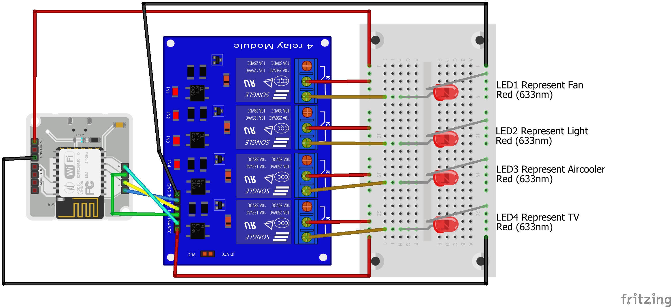
Step 2: Let's start with the connection of the relay module to the Bolt IoT device.
- Connect GND of Relay to GND of Bolt
- Connect VCC of Relay to 5V of Bolt
- Connect IN1, IN2, IN3, and IN4 of Relay to pin 1, 2, 3, and 4 of Bolt respectively.
In order to demonstrate the model I have used LEDs with the Relay however, we can use the home appliances like Fan, Light, etc.
As you can see in the picture below, every relay has 3 terminal NC(normally close), NO(normally open), and Common.
- +5 volt is given to the Common terminal of the relay and NO is connected with Anode of Led and Cathode of Led is connected to the ground.
- Connect all the relays respectively, refer below figure.
Final schematic looks like this :
Step 1: Connect the Bolt device with a 5 volt supply and open the BoltCloud https://cloud.boltiot.com/
Check whether the board is online or not. The green dot represents Bolt is connected with Bolt cloud through the Internet.
Step 2: Refer this link to know how to create a new product(project) on Bolt cloud https://docs.boltiot.com/docs/adding-a-product
Step 3: In this project, I have created a project named HomeAutomation
Step4: Configure your product as shown in the figure:
Step5: Click on the code and enter the details as shown in the figure:
Step6: Finally, Link the product to the device and upload the configuration visit https://docs.boltiot.com/docs/link-device-to-a-product
Code & Working:In the given code I have designed input buttons that can call the specific functions when they are pressed.
When the button is pressed, it sends a logic '0' to the relay which turns on the respective relay and changes its status according to logic. This way it works as an indicator button.
This project can be a good example for a beginner who wants to understand how to use HTML and Javascript together to design automation projects related to Bolt IoT.
Future scope:Based on this project an automation panel can be designed which can show the energy consumption and utilization time of each appliance are connected.


Comments
Please log in or sign up to comment.