


Logic gates are the fundamental building blocks of digital circuits. They are essentially tiny electronic switches that perform basic logical operations on digital signals, which are represented by two voltage levels: high (typically 5V) and low (typically 0V). They perform basic logical functions that are fundamental to digital circuits.
In a circuit, logic gates work based on a combination of digital signals coming from its inputs. Most logic gates have two inputs and one output, and they are based on Boolean algebra. At any given moment, every terminal is in one of the two binaryconditions: true or false. False represents 0, and true represents 1.
Depending on the type of logic gate being used and the combination of inputs, the binary output will differ.
Logic Gate Evaluation BoardUnleash Your Inner Digital Architect: Dive into the world of digital circuits with the Logic Gate Evaluation Board, featuring a comprehensive arsenal of 14 logic gates. Explore the fundamental building blocks of digital devices – AND, OR, NOT, XOR, NAND, NOR, and XNOR – and craft intricate circuits to experiment with a wide range of logic operations.
Effortless Input and Output Control: The board boasts 6 interactive inputs, each meticulously equipped with push buttons, reliable switches, clear LEDs for visual feedback, and secure banana sockets. This intuitive setup empowers seamless interaction and effortless connection to external components.
Designed for All Levels: Whether you're a curious beginner or a seasoned digital explorer, this board caters to your needs. Its user-friendly design features an ergonomic layout and an intuitive interface, ensuring a smooth learning experience for all.
Power Up Your Exploration: Enjoy the flexibility of powering the board with either a convenient USB connection or a versatile 6-12V external adapter. This ensures you have the right power supply for your specific project requirements.
Igniting the Spark of Education: The Logic Gate evaluation board is a perfect companion for educational institutions. Students of all levels, from budding minds in school to future engineers in universities, can leverage this board to grasp the core concepts of logic gates and digital electronics in a compelling way.
Learn basic logic gates with the Evaluation Board1. AND gate
2. OR gate
3. XOR gate
4. NOT gate
Do experiments with combinational circuits and observe outputs.
Example 1Experiment with basic logic operations: Try out the truth tables for different gates by setting the inputs (switches) and observing the output LEDs. See how changing the inputs affects the output for each gate type.
Build simple digital circuits: Following diagrams or tutorials, connect the gates using jumper wires on the development board.. This allows you to create circuits that perform specific functions like light dimmer, alarm.
Learn about digital logic design: The board provides a hands-on way to understand how logic gates work together to create more complex functionalities. You can test and troubleshoot your circuits to solidify your understanding.
Prototype your own designs: Once you're comfortable with the basics, you can use the board to experiment with your own logic circuit ideas. This is a great way to develop your skills in digital design.
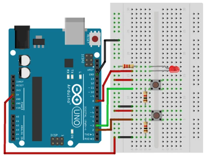
We can also simulate logic gates with an Arduino Uno. What are the advantages learning logic gates using LogicCraft Logic Gate Evaluation Board over simulate logic gates with an Arduino?- It is easy to get started with Logic Gate dev board for and beginner.
- Can build simple combinational circuits easily and quickly with the development board.
- Has no complexity so beginners can easily learn logic gates.
- No need knowledge about programming.
- Upload the below code to your Arduino board.
- Open the serial monitor in your Arduino IDE (usually at 9600 baud).
- Press the buttons connected to input pins and observe the output on the serial monitor.
const int inputA = 2; // Input A pin
const int inputB = 3; // Input B pin
const int outputPin = 7; // Output LED pin (optional)
void setup() {
Serial.begin(9600); // Initialize serial communication
pinMode(outputPin, OUTPUT); // Set output pin as output (optional)
}
void loop() {
// Read input states
int a = digitalRead(inputA);
int b = digitalRead(inputB);
// Simulate logic gates
int andOutput = a & b;
int orOutput = a | b;
int notA = !a;
// Print results to serial monitor
Serial.print("Input A: ");
Serial.println(a);
Serial.print("Input B: ");
Serial.println(b);
Serial.print("AND Output: ");
Serial.println(andOutput);
Serial.print("OR Output: ");
Serial.println(orOutput);
Serial.print("NOT A Output: ");
Serial.println(notA);
// Optional: Write output to LED (replace with your desired logic)
// digitalWrite(outputPin, andOutput); // Example: Light LED only for AND output
delay(5000); // Add a delay for better readability
} 


Comments
Please log in or sign up to comment.