


Hardware components | ||||||
 |
| × | 1 | |||
Hearing all that buzz about the new USB Type C port was quite interesting. There are many features and technologies integrated into this single port which will be on most if not all new products coming out in the near future. Cabling becomes an issue when so many different devices, power requirements and connections are needed and then we end up having a rats nest of wires.
Developing power hungry electronic devices requiring the ability to run from USB port, conventional methods were not feasible. Much research and testing led me to using the new USB Type C port which gives the ability to supply power in and have the ability to also be a host to connect with and supply power to peripherals. Many new mobile phones and laptops will be integrating USB Type C in their upcoming products. USB Type C also has superspeed data lines which were not implemented here due to the Raspberry Pi limitations.
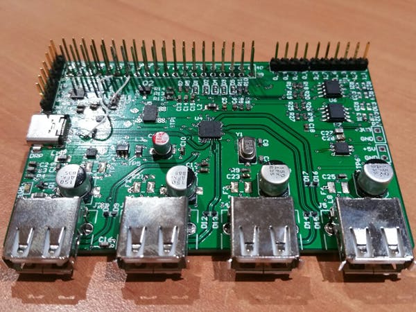
USB Type will allow you to provide more current and charge devices faster while allowing other USB and Video communications to operate simultaneously. As there were not many products out there for the Raspberry Pi with USB Type C functionality, I have developed a small hybrid USB Type C hub which can provide speeds of up to 480Mbps and 3A of power. This development board can switch power supplies on the fly and also includes either a PSOC or Atmel microcontroller to allow analog and digital signals to be sent to the Raspberry Pi via I2C bus.
In our setup we have a Raspberry Pi Zero which only has one USB micro connector attached to the PiCHUB expanding the USB outputs to include the USB Port. We show power switching on the fly while the python code is run on the Raspberry Pi to switch the USB Type C port from device (sink) to host (source) depending on what is connected. There is also a simple interrupt driven C code on the PSOC 4000 to flash an LED every few seconds.
The Raspberry Pi can now interface and control/communicate to devices with USB Type C ports. Python SMBUS and I2C must be configured and installed on the Raspberry Pi in order to control the USB Type C port.
Here are a couple good links on setting up the I2C:- https://learn.sparkfun.com/tutorials/raspberry-pi-spi-and-i2c-tutorial
sudo apt-get update (get the latest files and support)
sudo apt-get install python-smbus python-dev i2c-tools (using Python 2.7)
- Plug the PiCHUB onto the Pi Zero (or any other Raspberry Pi)
- Connect the Micro USB cable to "UP" upstream port on the PiCHUB and to the Pi Zero USB port
Note: if using the Raspberry Pi Zero, it must NOT be in Gadget mode otherwise the USB jumper cable will not work
At the command line, type:
sudo i2c-detect -y 1 (SDA - Pin 3, SCL - Pin 5, using i2c bus number 1)
Two I2C addresses should appear, one for the USB Type C port controller IC and the other for the microcontroller onboard. Address 0x60 is for the USB Type C port controller IC which the Python code will use to control.
Running the Python Script:This Python script should be put in the rc.local file on the Raspberry Pi so it is run upon bootup and the PiCHUB will work automatically. It can also be run from the command line if the PiCHUB is used occasionally.
Here is a link on adding the script to the rc.local file: https://www.raspberrypi.org/documentation/linux/usage/rc-local.md
At the command line type
sudo python i2c_comms.py
The python code will now run silently in the background waiting for a connection on the USB Type C port.
Components that were used in this project:1. Raspberry Pi Zero (Any Rasp Pi will work)
2. PiCHUB Development Board
3. USB Micro to USB A cable
4. USB Keyboard/Mouse Wifi Dongle
5. USB Type C Power Adapter 15W
6. Python C code for USB Type C Port Control (incld. in development kit)
- PiCHUB bottom view with Raspberry Pi Zero. An HDMI to min HDMI with DVI adapter for the monitor connection and a USB micro to USB A male jumper cable. Extended 2x20 pin headers plug in directly to the Pi Zero allowing to use some of the GPIO which are not used by the PiCHUB.
- PiCHUB side view showing USB Type C mid-mount connector. The 4 and 3 pin headers to the left are for the microcontroller programming via external programmer. The I2C on the microcontroller is also connected to the Pi Zero allowing interface of digital and analog IO.


Comments
Please log in or sign up to comment.