

Hardware components | ||||||
 |
| × | 1 | |||
 |
| × | 1 | |||
| × | 1 | ||||
 |
| × | 1 | |||
 |
| × | 1 | |||
 |
| × | 1 | |||
 |
| × | 1 | |||
 |
| × | 1 | |||
| × | 1 | ||||
| × | 1 | ||||
Software apps and online services | ||||||
 |
| |||||
| ||||||
| ||||||
| ||||||
| ||||||
| ||||||
The project has mainly three functionalities-
- To control the intensity of the LED, based on the brightness of the surroundings i.e if the brightness is less, the LED intensity will be high and if the brightness is more, the LED intensity will be less.
- To alert through the mail if the brightness of the surroundings changes suddenly using Z-score analysis.
- To turn the LED ON, OFF or control automatically using Google Assistant.
3. Controlling the intensity of the LED and alert through the email for the sudden change in the brightness
To control the intensity automatically we first have to measure the brightness of the surrounding that is measured using the LDR (Light Dependent Resistor). And then the intensity of the LED is changed according to the LDR response. So, first of all, let's see the circuit connection.
3.1 Circuit Connection:
- One leg of the LDR is connected to the 3.3v pin of the Bolt module and the other leg to the 'A0'.
- A 10k ohm resistor is connected between the 'GND' pin and the 'A0' pin of the Bolt module.
- The smaller leg of the LED is connected to the 'GND' pin and the larger leg is connected to any of the digital pins say pin 2 through a 330-ohm resistor.
3.2 Algorithm for Controlling the intensity according to the brightness and alerting:
- The latest LDR value is fetched from the Bolt device using the 'analogRead()' function.
- The sensor value is stored in a list, that will be used for computing z-score.
- LDR value is mapped with the LED intensity and the 'analogWrite()' is performed with that intensity.
- The z-score and upper and lower threshold bounds for normal and anomalous readings are computed.
- It is checked if the sensor reading is within the range for normal readings.
- If it is not in range, alert mail is sent.
- All the steps are repeated from step 1 after waiting for 10 seconds.
Before implementing the algorithm, we should make a configuration file which will have the specific keys for each user. We will import this file in our main code and use the various attributes.
3.3 Creating the Configuration file:
The configuration file is created using the following command on the ubuntu server.
sudo nano conf.py
The configuration file is like this.
MAILGUN_API_KEY = 'xxxxxxxx'
SANDBOX_URL = 'xxxxxxx'
SENDER_EMAIL = 'xxxxxx'
RECIPIENT_EMAIL = 'xxxxxx'
API_KEY = 'xxxxxxx'
DEVICE_ID = 'BOLTxxxx'
FRAME_SIZE = 10
MUL_FACTOR = 1
The ' MAILGUN_API_KEY is found in the API keys section of the mailgun dashboard.
'SANDBOX_URL' is found in the dashboard of the mailgun account.
'SENDER_EMAIL' will be 'test@SANDBOX_URL'. The details about how to create an account on mailgun are given on https://trainings.boltiot.com/courses/429176/lectures/6656741
'API_KEY' is found in the API section of the Bolt cloud.
'DEVICE_ID' is found in the 'Device' section of the Bolt cloud.
'FRAME_SIZE' and 'MUL_FACTOR' is used for Z-score analysis.
3.4 Mapping of the LDR value with the LED intensity:
As the LDR value varies from 0 to 1024 and the LED intensity varies from 0 to 255 and we need the lowest intensity for the highest brightness, LDR 0 is mapped with LED 255 and LDR 1024 is mapped with LED 0 and all the intermediate values are mapped used the following formula.
LED intensity = 255-(LDR response/4)
3.5 Detecting sudden change in brightness using Z-score analysis:
The following parameters are used for the Z-score analysis.
1. Vi denotes the LDR responses.
2. r is the frame size.
3. Mn denotes the mean of the LDR responses.
4. C is the multiplication factor.
5. Zn is the Z-score i.e the standard deviation of the LDR responses multiplied with the multiplication factor.
6. Tn indicates the upper bound (Vi+Zn) and the lower bound (Vi-Zn).
The formulas are like these.
3.6 Code for controlling the intensity of the LED and alerting for a sudden change in the brightness:
To write the code, we first have to make a python file (say auto_func.py) using the following command in the ubuntu server.
sudo nano auto_func.py
The complete code for the above functionality is written following the above-mentioned algorithm and is provided in the 'Code' section.
2.7 Output screen-shots of the python code:
4.1 Concept of Multiplexer:
To turn the LED ON or OFF we should use digitalWrite() and we can use any digital pin. As digital pin 2 is used for automatic intensity control, so we can use digital pin 1 for the ON and OFF functionality. But the problem is only one pin can be used at a time to connect the LED. So, we have to use the concept of the multiplexer and the digital pin 0 as the select line.
When the select line i.e digital pin 0 is in the LOW state, input 0 becomes the output of the multiplexer i.e automatic controlling of the LED takes place. Similarly, when the select line i.e digital pin 0 is in the HIGH state, input 1 becomes the output of the multiplexer i.e ON and OFF functionality of the LED takes place. If the digital pin 1 is HIGH, the LED becomes ON and if the digital pin 1 is LOW, the LED becomes OFF.
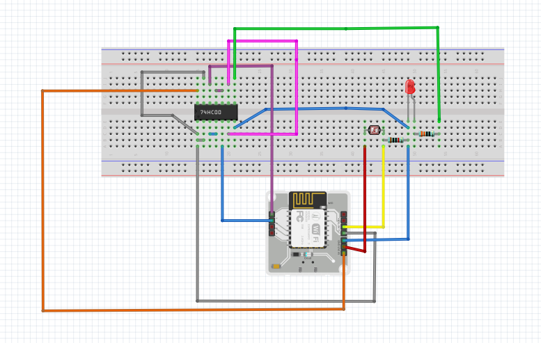
4.2 Implementation using basic gates and modification in the circuit diagram:
The multiplexer can be implemented using basic gates. The boolean representation of the above multiplexer is P0'.P2+P0.P1 where P0, P1, P2 represents the pin 0, 1 and 2 respectively.
So, the circuit connection is as follows.
The above circuit is the same as the following circuit.
The above circuit can be designed using only NAND gates as follows.
So, instead of using AND, OR and NOT gate, we can use only NAND gate i.e the 7400 IC (NAND gate IC).
The complete modified circuit is given in the Schematics section.
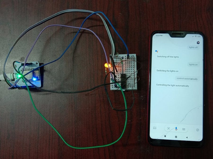
4.3 IFTTT Integration via Google Assistant and Webhooks:
We should have to go to IFTTT and create a new applet by clicking here.
Steps:
- After logging into the Google account we should click onto the ' +this' to create the trigger.
- Choose Google Assistant and then choose ' Say a simple phrase'.
- We have to type the phrase we want to trigger the action and then 'Create Trigger'. The trigger commands in different ways-
a) Control automatically
b) Automatically control the light
c) Control the light automatically
- Then after clicking '+that', we should choose 'Webhooks' and make a web request.
- Now, we have to create the GPIO control command.
The structure of the command is:
https://cloud.boltiot.com/remote/API_KEY/digitalWrite?pin=PIN_NUMBER&state=HIGH/LOW&deviceName=DEVICE_ID
In the case of automatic intensity control, the PIN_NUMBER will be 0 and the state will be LOW for our case. API_KEY and DEVICE_ID can be known from the Bolt cloud discussed in the configuration file section.
The 'Method' will be GET and the 'Content type' will be Application/json.
Steps to turn ON the LED:
We have to create another Applet. All the steps will be the same as the previous one but the URL should be changed. We have to use 'digitalMultiWrite' instead of 'digitalWrite' and make the 0 and 1 pin as HIGH.
Sample URL:
https://cloud.boltiot.com/remote/f1f918e9-d9c2-4e5b-aed0-b7cb743f74cf/digitalMultiWrite?pin=0, 1&state=HIGH, HIGH&deviceName=BOLT13819450
Steps to turn OFF the LED:
In this case, we have to use 'digitalMultiWrite' instead of 'digitalWrite' and make the 0 as HIGH and 1 pin as LOW.
Sample URL:
https://cloud.boltiot.com/remote/f1f918e9-d9c2-4e5b-aed0-b7cb743f74cf/digitalMultiWrite?pin=0, 1&state=HIGH, LOW&deviceName=BOLT13819450
To understand how to create an API command link to turn on or turn off a pin of the Bol, this can be followed.
After making all the three applets the applet page of IFTTT will be like this.
By saying "OK Google" and saying the phrase we had set while creating the trigger we can control the LED.
We have seen how to ON, OFF and control the intensity of the LED according to the brightness of the surroundings using Google Assistant and Bolt. We can use the same concept to control the home lights by using an additional device called solid-state Relay.


Comments