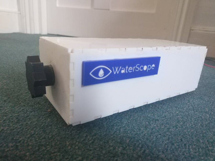
One of the most used instruments in a microbiology laboratory is the microbiological incubator, it is used for bacteria growth, incubation of cells and tempered storage. This project aims to create a incubator that can be fabricated in a typical makerspace environment at a low cost while achieving the same performance as commercial units. The incubator features a parametric CAD design to allow the users to modify it depending on their volume requirements. Finally, the proposed incubator has two power options: mains-powered mode and battery powered mode for portable instrumentation in remote environments.
The incubator is designed in Autodesk Fusion 360 which is free to use by hobbyist users, academics and small startups. The user is able to select parameters related to the incubator dimensions. The incubator is designed in such way that it allows fabrication by a laser cutter and easy assembly. Currently, the incubator is tested only using acrylic however significant performance improvement can be achieved if Styrofoam is used instead. The latest version of the design files is available here: http://a360.co/2z1mDeq The figure above shows the main body components of the portable incubator. The first three components on the left have to be lasercut twice, the fan/heater holder and heater guard once, and the rails 6 times (4 times for the inside of the incubator to create glass slide holders and 2 times for the bottom of the incubator to create legs for thermal). The prototypes of the incubators were lasercut with 3 mm acrylic, the parameters for the laser cutting depend on the machine you are using but you want to use the lowest power/speed settings to ensure a good fit between the components. Once you have cut the different parts, they can be assembled and glued with superglue. You can buy an off-the-shelf acrylic glue but superglue works just as fine and you can get 8 tubes for £1 from Poundland.
ElectronicsIn order to keep the project accessible to everyone, the electronics were kept to a bare minimum and only a pair of wire strippers and a screwdriver are needed (no soldering required). There are 6 main components which are shown on the figure below. The cheapest place to buy these components is from eBay or Aliexpress and the total cost comes down to approximately £30 including a mains power supply/charger and portable battery pack.
- 3D printer heater element - £2.35
- Power bank - £8.49
- Arduino Nano - £3.28
- 5V 40 mm computer fan - £1.78
- DS18B20 temperature sensor - £1.38
- Mains power supply – £3.38
- Mix jumper cables - £4.98
The connection between the different components is described in the schematic below, the connection between individual components can be made using jumper cables. For the connection between the power bank/mains charger one requires stripping one end of an USB cable and exposing the power wires (red and black). These can then be twisted together with Male to Female jumper cables and screwed to the Vin/GND ports of the IRF520 (circled in black) and the 5V/GND ports of the Arduino. In addition, the fan should also be connected to the Vin/GND ports of IRF520.The wires for the heating element should be shortened, stripped and connected to the V+/V- of the IRF520 board (circled in orange). The SIG pin of the IRF520 (circled in blue) should be connected to the Arduino pin D2 using a Female-to-Female jumper cable, additionally the GND cable adjacent to the SIG/VCC should also be connected to the Arduino.
Finally, the temperature sensor should be connected to the Arduino with Female-to-Female jumper cables. It is important to also connected a resistor (~4.7 kOhms) between the DQ pin of the sensor and the 3.3V power pin (it can be avoided if you follow this guide: https://wp.josh.com/2014/06/23/no-external-pull-up-needed-for-ds18b20-temp-sensor/ but it is not tested). This can be done as shown on the photo below, please ensure that the temperature body itself is covered with insulation tape (this is a temporary solution until a better sensor packaging is developed). The DQ pin should also be connected to D10 of the Arduino.
Performance and software functionalityThe performance of the assembled incubator was measured overnight; the temperature was set to 38 degrees setpoint and the resulting temperature fluctuations in the incubator were recorded over 12 hours. The ripple in the temperature is approximately 0.25 degrees which is below the noise limit/accuracy of the temperature sensor. The warm up time of the incubator was approximately 24 minutes which could be significantly improved if the incubator is insulated better. The average power consumption is approximately 0.7 A at 5V (varying between 0.3 A and 1.2 A depending on the ambient temperature) suggesting that the incubator is not insulated efficiently from the surrounding. For a 10,000 mAh power bank one can expect approximately 10 hours of operation but this may vary depending on whether the battery has a true capacity and the ambient temperature. The current version of the incubator relies on thermal insulation provided by the acrylic sheet however future plans including adding a layer of Calcium-Magnesium Silicate Thermal Insulation which should significantly improve the insulation or adding an air gap by using thinner two 2 mm sheets of acrylic instead of a single 3 mm.
Photos of the incubator
Biomaker Challenge 2017: Team 41
 Jim Haseloff


_t9PF3orMPd.png?auto=compress%2Cformat&w=40&h=40&fit=fillmax&bg=fff&dpr=2)


_1x_bGT19vVAby.png?auto=compress%2Cformat&w=40&h=40&fit=fillmax&bg=fff&dpr=2)
Comments
Please log in or sign up to comment.