I got some LoRa modules with SPI communication interface. One of the options it would have been to connect them to my Raspberry Pi. But, I didn't really liked the idea because I already had some stuff connected to my Raspberry Pi, and this starts getting unmanageable.
So, I decided to create a LoRa-to-Ethernet gateway that can be connected directly to a home router. The WIZ750SR module with its Ethernet interface and Cortex-M0 SoC was a great candidate to implement such a device.
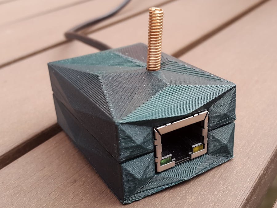
Here are some pictures with the resulting LoRa-to-Ethernet Gateway:
But, lets see how we got here...
LoRaLoRa is relatively new long-range low-power wireless technology.
According to Wikipedia,
LoRa uses license-free sub-gigahertz radio frequency bands like 169 MHz, 433 MHz, 868 MHz (Europe) and 915 MHz (North America). LoRa enables very-long-range transmissions (more than 10 km in rural areas) with low power consumption. The technology is presented in two parts — LoRa, the physical layer and LoRaWAN, the upper layers.
In this project I implemented an Ethernet interface for the LoRa physical layer. This has the advantage that allows just using the LoRa PHY with our custom messages, but also allows implementing LoRaWAN if we want so.
The LoRa ModulesI used two 433 MHz modules purchased from AliExpress. The boards are powered by the Semtech SX1278 chip.
After attaching a ribbon cable to the board and some pin headers to the other end the boards were ready for testing.
The LoRa Module is connected to the Arduino boards as follows:
- VCC - 3.3V,
- GND - GND
- SCK - SCK
- MISO - MISO
- MOSI - MOSI
- NSS - pin 10
- NRESET - pin 9
- DIO0 - pin 2
I used two Arduino boards (a ChipKit Uno32 and a Genuino 101) and the arduino-LoRa library to test the boards.
The sketch I used (attached to the project) is a sightly modified version of one of the examples coming with the arduino-LoRa library. It allows sending and receiving messages over LoRa using the Serial Monitor:
Note: the board uses the SPI interface and some GPIO pins for communication. This is not "exactly" the TTL serial interface supported by the WIZ750SR, but we will see how to fix this.
The WIZ750SR Module and the W7500P SoCThe WIZ750SR is a Serial-to-Ethernet module from WIZnet:
The board allows controlling serial devices over an Ethernet network, but with a custom software is capable of much more than that.
The board is powered by the W7500P SoC. The W7500P, according to its datasheet, uses an ARM Cortex-M0 core and along UART also supports I2C, SPI and standard GPIO.
The SPI1 unit of the W7500P uses the same pins as the UART0 module (CTS = PA_11, RTS = PA_12, TXD = PA_13, RXD = PA_14) used in WIZ750SR module. This means that after some tweaking in the software we can use those pins for SPI communication.
Along with SPI pins, we need 3 more pins. We can use the A, B, C pins of the WIZ750SR module, which are standard GPIO pins (PC_13, PC_12 and PC_9).
After successfully getting through the Getting Started Guide, I started implementing the LoRa related functionality.
Implementing a LoRa-to-Ethernet Gateway with the WIZ750SRAs we seen before, the default firmware of the WIZ750SR does not support SPI, so we need to do some changes.
I used Eclipse CDT with the GNU MCU Eclipse plugin:
The first step was to create a new Cortex-M0 project and import official WIZ750SR code from: github.com/Wiznet/WIZ750SR.
After building the project, I uploaded the binary with the W7500_ISP tool:
Of course it didn't worked at first. After multiple rounds of editing the W7500P specific system files and rebuilding the project, the WIZ750SR finally showed up in the WIZnet-S2E-Tool-GUI:
The next step was to change the code to communicate over LoRa instead of the UART. So, first I ported the arduino-LoRa library to work with the W7500P, then I changed the rest of the code to send / receive data over the LoRa interface.
The rest of the WIZ750SR code is unchanged. This means all the non UART related feature are still available and can be configured from the WIZnet S2E Configuration tool.
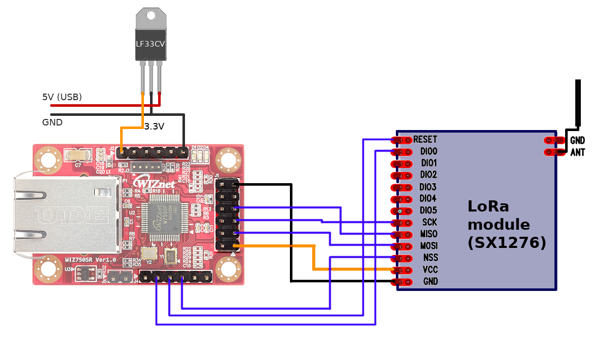
The LoRa module is connected to the WIZ750SR as follows:
- VCC - VDD,
- GND - GND
- SCK - RTS / SCK (PA_12)
- MISO - TXD / MISO (PA_13)
- MOSI - RXD / MOSI (PA_14)
- NSS - A (PC_13)
- NRESET - B (PC_12)
- DIO0 - C (PC_9)
Using one of the Arduino LoRa test devices, I successfully tested the LoRa communication:
The final source code can be found in the linked GitHub repository.
Building a CaseThe testing setup was a wiring chaos (I forgot to take a picture). That was exactly what I wanted to avoid, so I decided to design a custom case for my Lora-to-Ethernet Gateway.
The case was designed in Autodesk Inventor and it was exported to .stl files. Then using Blender I added some design elements for better look. The edited models were exported to new .stl files.
The model has three parts:
- a bottom part
- a top part
- and a little stand for the LoRa module
The models were sliced in Cura and 3D printed on a Tevo Tarantula:
The .stl files are attached to the project
AssemblingThe next step was to get the parts ready for the assembly.
From the LoRa module I removed the pin header, shortened the ribbon cable and attached new pin terminations.
Using an old USB cable and an LF33CV 3.3V voltage regulator I built a simple power supply. The module gets its power from an USB port (5V), which is used as the input of the LF33CV. The 3.3V output is connected to one of the VDD pins of the WIZ750SR. The USB ground is connected both to the LF33CV and the WIZ750SR ground pins.
With this the Lora-Ethernet gateway was ready for assembly.
Here i a short animation with the assembly process:
After this the LoRa-to-Ethernet gateway was ready to use. We can use it either with raw LoRa or with can implement LoraWAN.
Use Case 1: Raw LoRa with Custom MessagesFor simpler application we can use LoRa modulation with or custom message type. This has the advantage that is easy to implement, but has some drawbacks too: offers no security example.
The Arduino + telnet example shown above uses LoRa with raw strings message.
In case we have multiple client devices, we can add some addressing. A good example is show in the LoRaDuplex example of the Arduino-LoRa library.
Use Case 2: LoRaWAN (The Things Network) GatewayFor more complex application the usage of LoRaWAN is highly recommended. It offers some important advantages over raw LoRa, such us advanced security, and globally unique addressing.
To use the device as a LoRaWAN Gateway we need the an application that connects both to our LoRa-to-Ethernet gateway and to the The Things Network servers.
The Things Network is a LoRaWAN based, community driven IoT network:
The Things Network is a global, crowd-sourced, open, free and decentralized internet of things network.
First we need to register a new gateway in the TTN Console:
We need to enter a unique, 8 byte gateway ID, and as we will use the legacy packet forwarder, the "I'm using the legacy packet forwarder" checkbox must be checked.
To connect to the TTN network I used a sightly modified version of the single_chan_pkt_fwd project. I added some code to connect to out LoRa-to-Ethernet gateway and forward the packets to the TTS servers:
        uint8_t receive_buffer[2048];
	int len;
        while (1) {
		if ((len = recv(socket_desc, receive_buffer, 2048, 0)) > 0) {
			printf("\nReceived %d:\n", len);
			print_buff(receive_buffer, len);
			uploadPacket(receive_buffer, len);
		}
                ...
        }
The app sends status messages too, so after starting the app our gateway should show up as connected in the TTN console:
Now we can send some messages from our LoRa test device. We case use the ttn-abp example from the Arduino-LMIC library, with the frequency set to 434 MHz.
The sample messages sent by the Arduino test device will be received by the LoRa-to-Ethernet gateway. The Lora-to-Ethernet gateway forwards the TTN gateway app connected over TCP, which forwards the packets to the TTN server over UDP:
Gateway ID: aa:bb:cc:dd:cc:dd:dd:dd
Listening at SF7 on 434.000000 Mhz.
------------------
Connected
Received 26:
40:01:00:FF:03:80:48:00:01:8B:01:16:1D:BE:44:2E:28:33:E1:9B:99:3C:2B:E0:58:C7
rxpk update: {"rxpk":[{"tmst":1238904561,"chan":0,"rfch":0,"freq":434.000000,"stat":1,"modu":"LORA","datr":"SF7BW125","codr":"4/5","lsnr":1,"rssi":-25,"size":26,"data":"QAEA/wOASAABiwEWHb5ELigz4ZuZPCvgWMc="}]}
After this the packets will be shown in the Gateway traffic log and we can create Applications to consume them:
The full gateway app code and the Arduino sketch are attached to the project.
Cheers!


Comments
Please log in or sign up to comment.