One of the main advantages of a magnetic sensor is that needs physical contact points to precisely measure movements in three dimensions.
This inspired the idea to build an TrackBall device using the Infineon TLE493D 3D magnetic sensor. A TrackBall device that allows controlling rotation in three axes. Such a device can be useful in CAD software, 3D design software, but also in games.
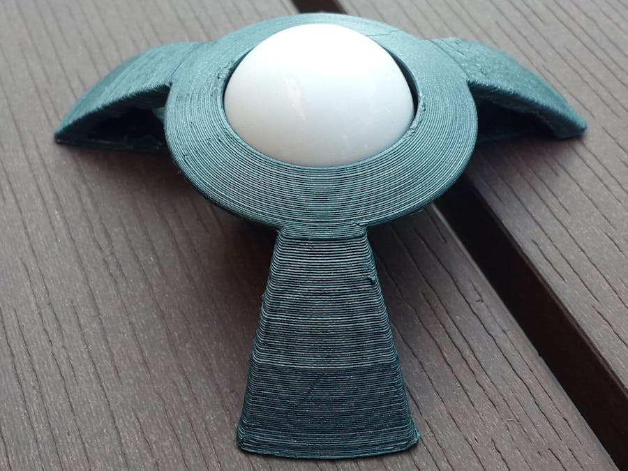
The device consists in a case and magnetic ball. The magnetic sensor is placed in the case and senses the movement of the magnetic ball.
The magnetic ball is built from a sphere neodymium magnet with a plastic cover on it.
As it's no needs to physical with the sensor, the device can be made to be more reliable and durable.
To be more convenient to use the devices uses Bluetooth Low Energy (LE) communication and compatible with many hardware and software the device is implemented as a standard Human Interface Device (HID).
Geometry
As the TLE493D measures the magnetic field in three dimensions, we will able to track the rotation the ball on three axes (sensorX, Y, Z). To be more convenient to the user we may want to translate the rotation into an other set of three axes (user X, Y, Z):
The formulas to calculate rotation along the sensor axes are:
rX = atan2 (bZ, bY)
rY = atan2 (-bZ, bX)
rZ = atan2 (-bY, bX)
(bX, bY, bZ are the magnetic field values read from the sensor)
(the formulas for the user axes rotation I didn't figured out yet :P)
PartsTo build the project we need the following parts:
The Sensor
The first part we need is the TLE493D 3D Magnetic Sensor. The TLE493D is capable to measure the magnetic field in 3 directions (X, Y, Z). Along that, the 12 bit precision and the low power consumption makes the sensor a good choose for the wireless input device.
The TLE493D sensor I used is part of a Sensor2Go board. The has line that can be cut if we want to use just the sensor.
The Magnet
The next thing we need is a magnet, of which magnetic field will be measured by the TLE493D sensor. I choose a 19 mm diameter sphere neodymium magnet:
This neodymium magnet has a two poles and a strong magnetic field, which allows us to get precise, high resolution measurements. As the TLE493D measures the magnetic field in 3 directions, based on the measurements we should be able to determine the rotation of the ball in 3 axes (X, Y, Z).
The magnet will a get a protective plastic shell and with this will make the ball part of the trackball device. (More on this later)
The Bluetooth SoC
The measurements made by the TLE493D needs to be processed by a micro-controller. I wanted a low power, wireless devices I choose a nRF51822 based Bluetooth Low Energy SoC module. The nRF51822 produced by Nordic, is an ARM Cortex M0 based SoC with built in Bluetooth LE stack and low power consumption.
The WT51822-S4AT, I choose, is a low footprint module based on the nRF51822 SoC. The board features 7 GPIO pins (with I2C support), which is more than enough to be able to communicate with the TLE493D sensor.
The Battery
To power the nRF51822 SoC and TLE493D sensor we need a battery. My initial idea was to use a CR2032 battery, which is a 3V Lithium based battery with relatively high capacity. As both the BLE SoC and the magnetic sensor are low power devices, the CR2032 battery should last enough time.
But, it turned out the using a CR2032 is NOT exactly a good idea. The problem is that the magnet from the ball interferes metal casing of the CR2032 and make the ball turn toward the battery. For this reason is decided to power the component externally.
In a version 2.0 of the trackball device a Li-ion battery with a non casing could be used. This would also allow recharging the device.
The 3D Printed Case
As we have the part list we can design a casing for them. Based on the part dimensions, the case was modeled in Autodesk Inventor and was be 3D printed from green PLA.
As we have the parts and the case design we can start building the project:
3D Printed Parts
The build process started with 3D printing the casing:
and the magnet shell:
The casing was printed in two parts a big bottom part and small top part. This was needed to be able to place the ball in his slot.
The casing was printed from Green PLA, while the magnet shell from white PETG filament.
I used support materials for both the prints, so I cleaned the parts using some pliers and sandpaper.
Magnetic Ball
To create the magnetic ball, he first step was to hold the two plastic parts and the magnet together.
- using sandpaper, finished the contacting faces of the plastic parts perfectly flat
- fixed the magnet in one of the plastic parts using super-glue
- using super-glue, glued the two parts of the shell together (with the magnet inside)
As the plastic shell was 3D printed, the surface of the ball was a little bit rough. So it was smoothed as follows:
- using a couple of sheets of sandpaper with increasing grit numbers (P100 -> P1500), I sanded the surface of the ball smooth
- filled the micro gaps / holes / cracks with super-glue, and let it dry
- to clean the excess super-glue, repeated the first step
At this point surface of the ball was completely smooth, but the contact line was still visible. To hide, after cleaning pall, I applied a couple of layers of white glossy spray paint:
At this point the ball was finished.
Electronics
After I tried the TLE493D sensor with the Sensor2Go board, it was time to cut sensor part of the PCB and try it out with nRF51 SoC.
To do the test with nRF51, first I soldered some pins to the TLE493D PCB and I used a bigger nRF51 development board. After, I confirmed that the I2C communication between the nRF51 and the TLE493D works it was time to move on to the WT51822-S4AT module.
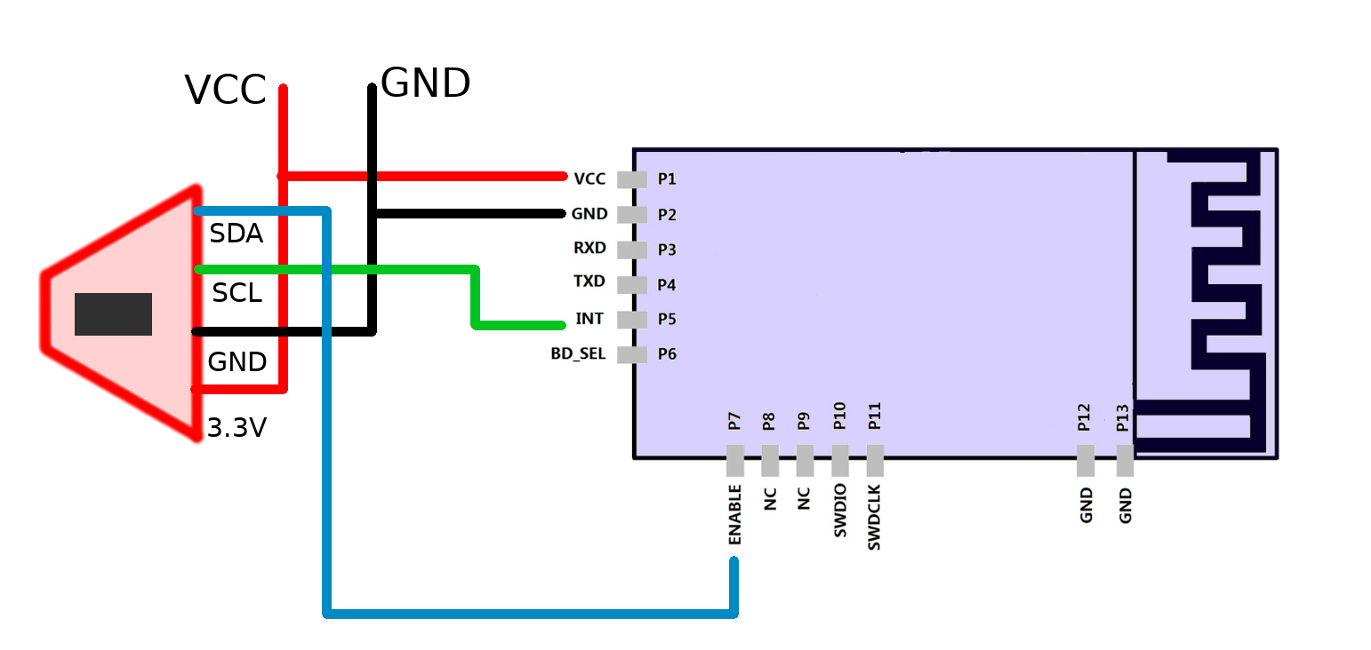
For this I connected the parts according to the following schematics:
Because the WT51822-S4AT has some pretty small pin cutouts, I used some thin wires extracted from an USB cable:
Assembling the TrackBall device
To assemble the device glued the TLE493D in his slow with some hot glue. Then I fit the WT51822-S4AT into his cutout.
The surface of the hole where the ball fits was smoothed out using the same sanding technique as used for the ball. This allows the ball to move smoothly with minimum force applied.
To finish the build I placed I put in the ball and fixed the top part of the casing with some double sided tape.
Here are some photos of the finished device:
The software running on the Bluetooth SoC was written in Arduino IDE. The SoC was programmed by the Serial Wire Debug (SWD) protocol using a ST Link V2 clone:
The trackball is implemented as a Bluetooth HID device (a joystick), using the nRF51 libraries from sandeepmistry:
- github.com/sandeepmistry/arduino-nRF5
and the TLE493D-W2B6 library from Infineon
The trackball HID device is implemented as a custom BLEHIDPeripheral as a new BLETrackBall class.
In the first implementation, the Rx, Rz, Ry values were just the raw X, Y, Z values read from the sensor. This was useful to see that we can read values from the sensor and transfer the over BLE and HID.
The next was to implement and test the rotation formulas:
rX = atan2 (bZ, bY)
rY = atan2 (-bZ, bX)
rZ = atan2 (-bY, bX)
(bX, bY, bZ are the magnetic field values read from the sensor)
Unfortunately, I did not had the time to fine tune the formulas and implement more advanced features like noise filtering.
Along with others we run into a very time consuming problem with most likely the TLE493D Arduino library. What happens is that the communication with the TLE493D stop working and is very hard to get it working again. More details here:
https://github.com/Infineon/TLE493D-3DMagnetic-Sensor/issues/6
DEMO
o, here is video how to Track Ball device works in the current forms:
Cheers!


Comments