

Hardware components | ||||||
 |
| × | 1 | |||
| × | 1 | ||||
| × | 1 | ||||
| × | 1 | ||||
| × | 1 | ||||
| × | 1 | ||||
| × | 1 | ||||
| × | 1 | ||||
Software apps and online services | ||||||
 |
| |||||
| ||||||
Hand tools and fabrication machines | ||||||
 |
| |||||
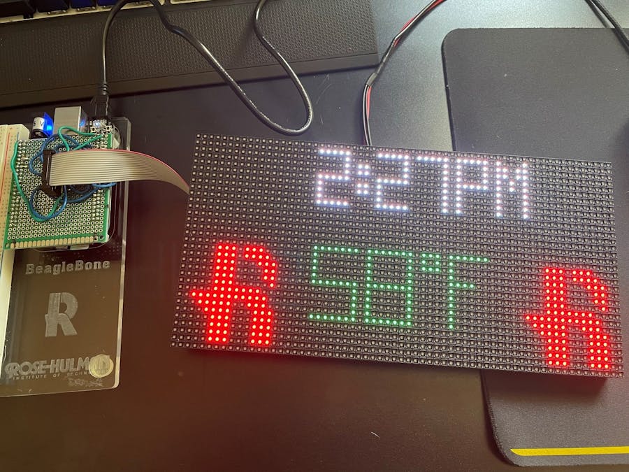
I just got done taking a class at Rose-Hulman Institute of Technology, ECE434 - 32bit embedded Linux. In this class, we used the BeagleBone Black to do various things. Like most classes at Rose-Hulman, this one ended with a final project; for this I decided to make a LED information display ran by the beagle. This project displays the current time, current temperature, and the Rose-Hulman logo on the LED matrix. I've wanted to do something like this for a very long time, but this class gave me information needed to do this. In case anyone else out there wanted to do something similar, I though that I would write up how I did this to save them of some of the headaches that I encountered!
Setting Up Falcon Player
To get started, you want to download the Falcon player image from the Falcon Player git repository. After downloading, flash the SD card with the image with a program such as Balena Etcher. If you want to be able to SSH into the Beagle and run the program exclusively on it, you can follow this tutorial on eLinux.org. When following Mark A. Yoder's tutorial instead of using the default debian as a username and the default password, the Falcon Player image has the following account set up.
- username: fpp
- password: falcon
At this time you can clone my project repository linked at the bottom of the page wither on the Beagle or the host computer.
CapeConstruction
This next part is the most tedious of the entire project, if you wish to just connect the matrix with breaboard wires, that will still work I just wanted something that would be reliable after disconnecting the cape multiple times working on other projects.
The picture below shows an example of what you want to end up with (hopefully your cable managing is better than mine)
I used an 8cm board from the listing that I linked to at the top of this project. The first thing that I did was to cut off one of the ends with surface mount pads on it right where the first row of exposed copper holes are on the board; this gives just enough room for the board to sit right up against the ethernet port on the Beagle.
Next comes the fun part, soldering. Starting off, you want to solder some header pins to the board, 4-23pin strips and 2-8pin strips and solder these to the PCB. This is where the fun really starts, below is my schematic of the data cable connector that the matrix uses. I soldered the connector with the top row of the connector being the closest to the cut side of the PCB. Treat the schematic as if you were looking at the top of the cape as it is plugged into the Beagle.
Reconfiguringthe Power Cable
My matrix came with a power cable with two connectors on it. I only plan on using one matrix for the time being, so I cut the code above and below the joint and re-soldered the connector with the terminal ends. Whether you decide to trim the cord like I did or not, cut the ends off of the terminal end of the power cord. You can either put different terminal ends on them that will fit into the terminal block, or you can do like I did and twist the wires and put some solder on it and stick those into the terminal block. Below is a picture of my completed power cable.
ConnectingEverything Together
From my reading, this matrix can be sensitive to power surges so it's recommended to attach the components in the following order.
- Connect the power cord to the matrix
- Connect data cable between the matrix and Beagle
- Connect the Beagle to the host computer/power
ConfiguringFalcon Player
On your host computer and with everything connected, navigate to "192.168.7.2", this should open up the Falcon Player interface. (You don't need to SSH into the Beagle) In the Falcon Player interface navigate to Input/Output Setup -> Channel Outputs, you should be at the screen below.
Configure your screen to look like mine does above, and make sure that "Enable Led Panels" is checked. If you scroll down, there is a section called LED Panel Layout, make sure that the arrow is pointed to the right.
Next it's time to test the display. Navigate to Status/Control -> Display Testing. On the left select "LED Panels" under Model Name, the end channel field should have changed to 6144. If you click on "Enable Test Mode" and your display blinds you with dancing red, green, and blue lights, congrats! Your display works! The photo below should give you an idea of what you're looking for at this stage in the setup.
Now, navigate to Input/Output Setup -> Channel Inputs. Here there should already be one universe set up, configure it with the following parameters.
- Active: Selected
- Input Type: E1.31 Unicast
- FPP Channel Start: 1
- Universe #: 1
- Universe Size: 96
At this point, this universe should look like the first one in the photo below.
With the first universe set, in Inputs Count set the number to 64. Now there should be 64 universes set up with the appropriate start and end channels. We have 64 universes because we want to update the display one column at at time. Each universe is of size 96 because each pixel has three LEDs(red, green, and blue) and each takes up one channel. Therefore, 32 rows per universe, and 3 LEDs per row, gives you 96 channels per universe.
With this set, you're ready to run the program!
Starting the Project
Start off by navigating to where you cloned the project repo earlier. Run the following line to install all of the necessary packages.
$host sudo ./install.sh Before running the program, in clockMatrix.py, change Terre Haute, IN in lines 12 and 242 to where you want the temperature data pulled from. Also you need to sign up on OpenWeather for an API key and replace "YOUR_API_KEY" in line 9 with yours.
To start the program, run the following lines.
$host chmod +x clockMatrix.py
$host ./clockMatrix.py
There's a chance that you might get an error about it not liking the "\r" character or something like that. To fix it run the following lines.
$host sudo apt install dos2unix
$host dos2unix clockMatrix.py
$host ./clockMatrix.py
If that didn't fix it, try running the following.
$host unix2dos clockMatrix.py
$host ./clockMatrix.py
Now you should have a working LED matrix clock!
Conclusion
This was a really interesting project, and I had fun tinkering around with the matrices. Even though this was much harder to figure out on my own that I had originally thought, it was definitely worth it.

Comments
Please log in or sign up to comment.