


Hardware components | ||||||
 |
| × | 1 | |||
| × | 1 | ||||
Software apps and online services | ||||||
 |
| |||||
| ||||||
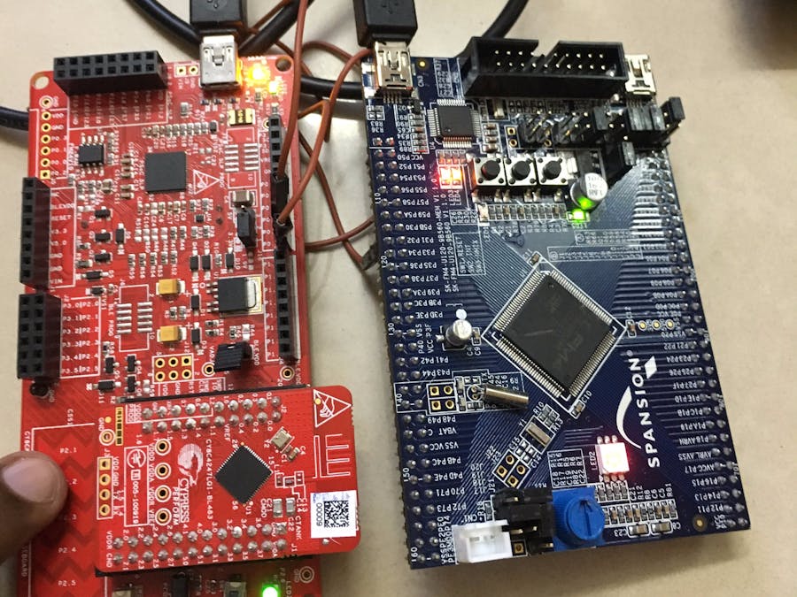
The code example demonstrates the UART communication between FM4 and PSoC 4 BLE. Both the devices are configured in Full Duplex Mode (Tx and Rx). Peripherals of the two devices are mutually controlled over UART.
OverviewIn the PSoC 4 BLE project, we use UART, TCPWM and Capsense. Capsense is configured as a Slider. In the FM4 project, we use ADC, Base Timer (BT) and UART.
Now, the Capsense Slider data is sent over UART from PSoC 4 BLE to FM4. The Base Timer is configured as a PWM in the FM4 project. The PWM output is connected to the on-board red LED. The Slider data is then used to update the PWM compare value and hence the LED brightness is controlled.
Similarly, the on-board potentiometer in FM4 kit is connected to an ADC and the 8 bit Digital value is sent from FM4 to PSoC 4 BLE over UART. This updates the TCPWM compare value at the PSoC 4 side and hence the LED brightness is controlled at PSoC 4 side, as well.
Requirements- Design Tool: PSoC Creator 4.0 or above, IAR Embedded Workbench for ARM or Keil uVision, PDL 2.1.0,
- Programming Language: C (ARM GCC 4.9-2015-q1-update – included with PSoC Creator), C for IAR
- Associated Devices: PSoC 4 BLE, MB9BF56xR
- Required Hardware: CY8CKIT-042-BLE, FM4-U120-9B560 - ARM® Cortex®-M4 MCU Starter Kit with USB and CMSIS-DAP
The project can be tested on the CY8CKIT – 042 BLE and FM4-U120-9B560 kits. Note that the project can be ported to any supported PSoC 4 or FM4 device. Make the following connections between the two kits:
- P0.4 in the -042 kit (UART Rx) is connected to P32 in the FM4 kit (SOT, Tx)
- P0.5 in the -042 kit (UART Tx) is connected to P31 in the FM4 kit (SIN, Rx)
The default pins are used for Capsense Slider. MFS3 is used in the FM4 project. Also, BT6 is used which has direct connection to on-board red LED (TIOA6_2). Also, ADC channel 18 is used which is connected to the on-board potentiometer (AN18).
The projects can be ported to any PSoC 4 or FM4 device (or kit) by making necessary changes in the Pins. Also, ensure that jumpers in FM4-U120-9B560 are correctly placed as shown under “Jumper – Default (Run mode, CMSIS-DAP)” in the Kit –User Guide that can be downloaded from here.
Project DetailsPSoC 4 BLE Project
Here, we have the UART configured with interrupt in Rx mode. Capsense is configured as a slider. The Slider data is sent over UART to FM4. Similarly, the ADC data from Potentiometer is received over UART and this controls the duty cycle of the TCPWM thereby controlling the LED brightness.
FM4 Project
The FM4 project also has the UART configured in both Tx and Rx mode. MFS3 is used for configuring the UART. The ADC is connected to the on-board potentiometer which uses AN18. Also, BT6 is used for configuring the PWM. The Capsense slider data is received over UART and is used to update the duty cycle of the BT. This is used to control the LED brightness. Also, the ADC data is transmitted to PSoC 4.
Build the ProjectsThe PSoC 4 project can be easily programmed to CY8CKIT – 042 BLE after building the project. However, for the FM4 project you need to consider the following:
1. The FM4 project attached here is based on PDL 2.1 template. The folder has three sub-folders names cmsis, drivers and mb9bf56xr (device folder). IAR was used for testing the project. Ensure that you set the necessary directory paths under “Preprocessor” in the Project Build Settings. Please provide the paths to these folders. This depends on where you save the project.
2. Ensure that mfs.c, adc.c, bt.c, pdl.c, etc. are added in the workspace.
3. For more details, you can refer to the PDL 2.1 Guide which can be downloaded from here.
Testing1. Make the necessary connections between the two kits.
2. Program the two kits. Run the FM4 kit in Run Mode.
3. Move the slider position in the PSoC 4 BLE kit. Observe that the red LED brightness in the FM4 kits is varied as you move the slider position.
4. Also, vary the potentiometer position in the FM4 kit. Note that the LED brightness in the PSoC 4 BLE kit is also varied.


Comments
Please log in or sign up to comment.