
Hardware components | ||||||
 |
| × | 1 | |||
| × | 1 | ||||
| × | 1 | ||||
| × | 1 | ||||
| × | 1 | ||||
| × | 1 | ||||
| × | 1 | ||||
| × | 1 | ||||
| × | 1 | ||||
Addressable LEDs, regardless of the driver used in them, accompany fans of electronics and DIY movements in many projects requiring LED lighting. Why are they so popular? It’s all in the capabilities of these drivers. There is a separate circuit for each diode. It allows you to identify each diode in the system, so you can control the color of each diode using a single microcontroller output only. To show how we can use addressable diodes we will build a simple clock. It will look similar to a 7-segment display.
What do we need to make the project?
After reading the introduction it's easy to realize that we need addressable diodes. We will use a convenient diode strip equipped with WS2812B chip.Arduino Nano with RTC module will be responsible for controlling the clock, and the case will be 3D printed.
Full list of components is available below:
Printing the clock componentsAt the very beginning we should print the clock components. Models are large, so we recommend using a printer with a larger workspace. At Botland we used Snapmaker A350. Printouts can be made of any color of filament - our choice was white PLA filament, which was additionally coated with varnish to make it smooth except for transparent elements made of transparent PETG material. All models are available on our Thingiverse profile. To get all the necessary elements for the project, we print:
4 x digital_top.stl - transparent material
4 x digital_middle.stl - base material
4 x digital_bottom.stl - base material
1 x dots_middle.stl - base material
1 x dots_bottom.stl - base material
1 x dots_top.stl - transparent material
1 x top.stl - - base material
1 x bottom.stl - base material
After printing we can process the models to make them look good. Deburrer will serve as a great tool for this, as it helps in fast processing and helps to smooth the prints’ edges.
Assembly of led strips and electronicsWe will start with creating the electronics part of the project by sticking and soldering the LED strips on the parts printed from the digital_bottom.stl file. We need 28 pieces of LED tape. Each must contain two diodes - two pieces of one diode length. If our tape is waterproof, then we need to remove the silicone layer on the contacts, and if we have a tape without silicone insulation, we can just skip this step. Glue and solder the tape as shown in the picture below.
When we have soldered the LED strips, then we can get down to our driver. At the very beginning let's prepare our universal board, set of wires, RTC module, power supply, set of goldpins and Arduino Nano board. Pin VIN of Arduino is connected to VCC of power supply, RTC module and led strip. The GND pin of Arduino is connected to GND from power supply, GND pin of led strips and RTC module. We connect A4 pin of Arduino with SDA pin, and A5 pin with SCL pin of RTC module. Finally, we need to connect the 6th pin of Arduino with DIN pin of the first led segment.
Uploading the code to the Arduino board
In order to work properly, we need some software which we upload to our board using Arduino IDE program.
Full code is available in coding section.
it is worth noting the following two lines of the code - to set the correct time we need to remove the "//" characters from before the code, but we do this only once, after setting the code we upload it again, so that every time the device is turned off the time won’t be set to 15:12.
//rtc.setHour(15); // Set the hour to 15 (24hr format)
//rtc.setMinute(12); // Set the minute to 12
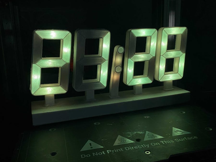
After uploading the code to the board and connecting the power supply to the mains, we can finally admire our self-made clock!


Comments