Create a low power battery operated modular LoraWAN node by using Seeed Grove system modules and the new Seeed Grove Base ATtiny3224 microcontroller board.
I recently repaired an old piece of industrial equipment. It puts labels on cans of beer. The control box was designed in a very modular way, a DIN rail with a PLC, DIN rail relays, a DC motor controller to control the conveyor belt motor, and two other motor controllers to run the labeling applicator.
It seemed complicated at first, and I did not know how to access the PLC program, but I found I could download documentation on each part or module and their functions. After a while I was able to diagnose a broken rotary encoder, and replace the malfunctioning part. Also, a motor controller was broken, and I was able to swap it for the identical part that was already present in the control panel for a motor driven peripheral that had never been installed. This project came with some free beer, so that was a bonus!
Later, another broken piece of machinery came my way, an ink labeling machine that squirts a “best before” date on cans of beer after they have been filled. This machine was a single monolithic PCB with many ICs and MCUs and what looked like an FPGA. And while it had a user manual, I was not able to find the fault as the pcb was very complicated. I still have the broken machine as I don’t want to contribute to e-waste and I still hope I might repair it. It saddens me that when I develop electronics, they will one day become e-waste.
This made me realize the value of modular systems, they can be repaired easily, and the individual parts can be swapped out or reused in other systems, instead of being thrown away. Modularity promotes repair, reuse, and circularity.
I am experimenting with building modular microelectronic systems by using the Seeed Grove system modules.
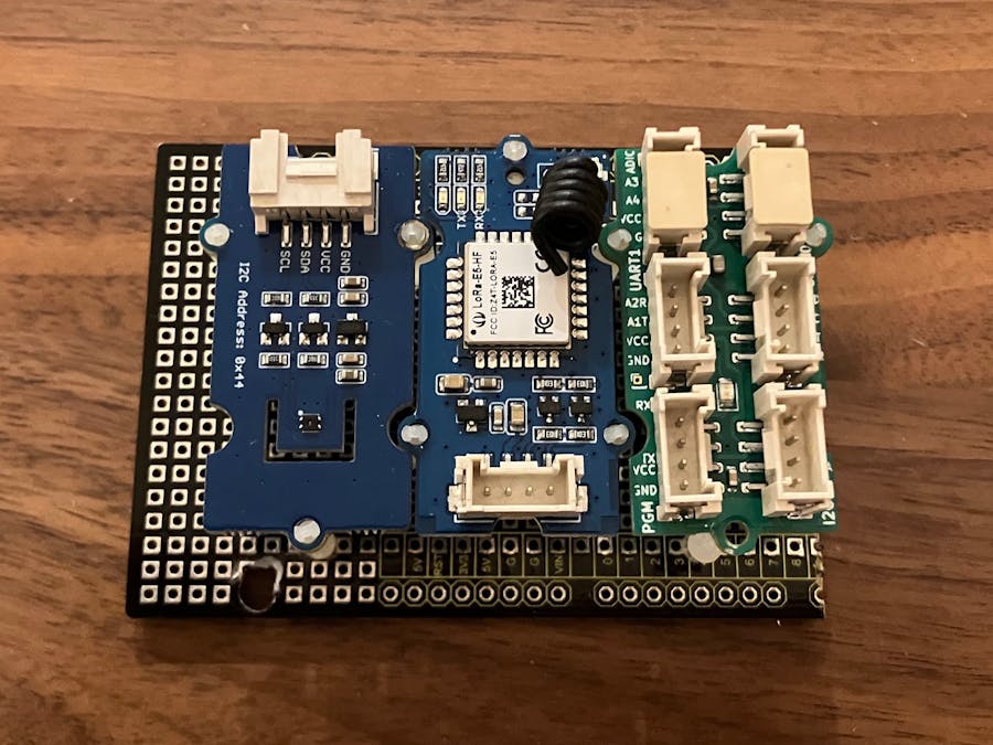
Here is an example battery powered LoraWAN sensor built in a modular design using three Grove system modules,
- an SHT40 temperature and humidity sensor,
- an AT command LoraWAN communications module (Wio E5), and
- a low power Grove Base ATtiny3224.
The Grove Base runs a simple program to copy readings from the SHT40 and send them as a LoraWAN uplink. I am hoping this sensor can become a production model to install at client locations, not just a prototype.
I was inspired by the following LoraWAN sensor nodes
- LSN50-V2 -- Waterproof Long Range Wireless LoRa Sensor Node https://www.dragino.com/products/lora-lorawan-end-node/item/155-lsn50-v2.html - modular with M.2 LoraWAN module
- The Things Network Generic Node - https://www.genericnode.com/
In order to make this system I needed to design the Grove Base ATtiny3224 to control the sensors and LoraWAN transceiver.
The Grove Base ATtiny3224 HardwareI developed the Grove Base Attiny3224 module as part of my entry to the Seeed Grove sensor co-invent campaign, it's a great opportunity for anyone to make your dreamed sensor a reality.
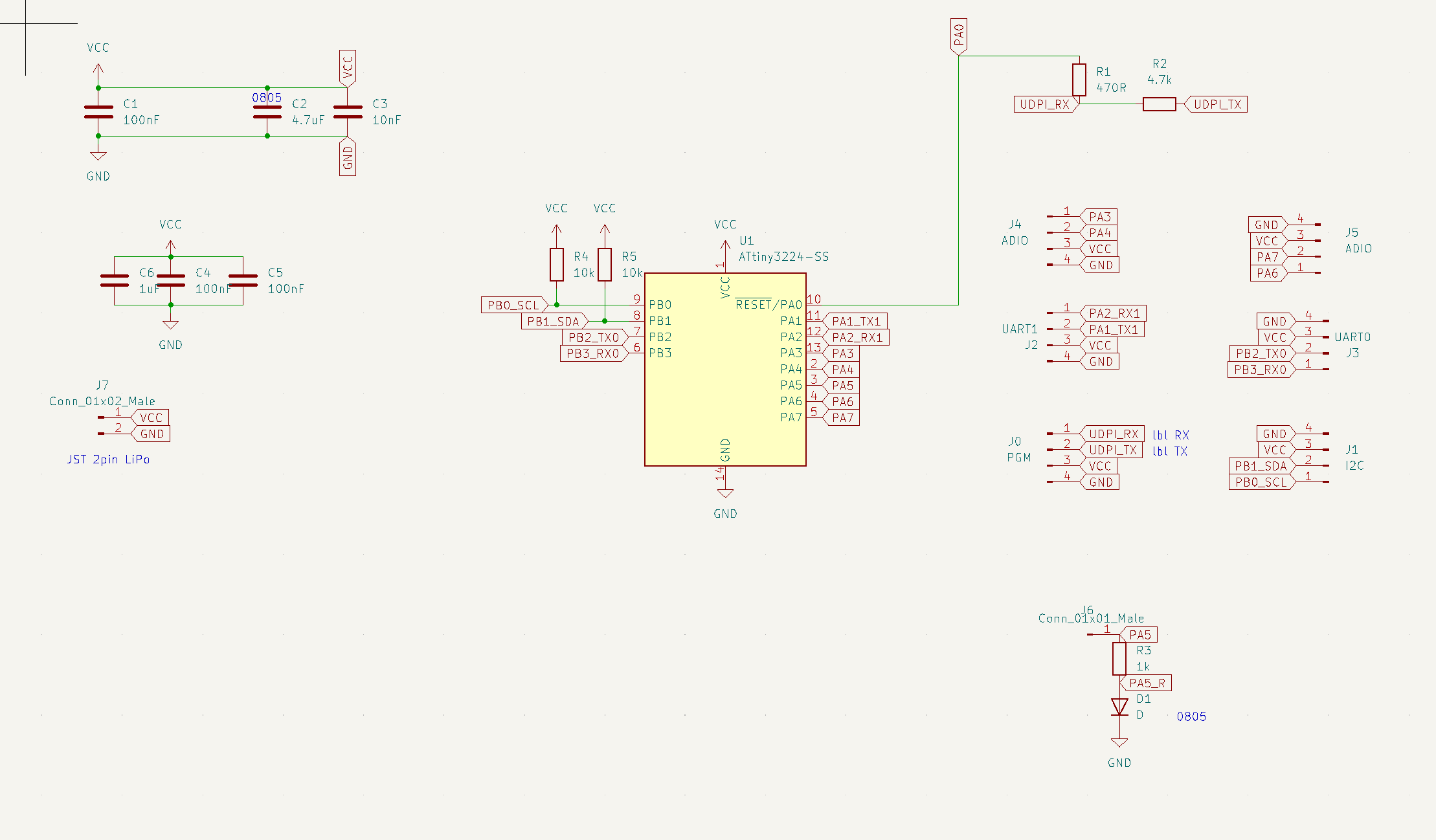
This module is based on the ATtiny tinyAVR 2-series 3224 MCU. It may only be 8-bit, but It is a powerful MCU that has an advanced differential ADC, programmable asynchronous logic, and can be run at very low power. It has one hardware I2C port, two (!) hardware UARTS, and five additional GPIOs that support ADC and PWM. The GPIOs allow for two additional general purpose Grove system ADIO connectors.
Luckily, the six Seeed Grove connectors to support these ports can just fit on a 2x1 Grove system module, below.
The Grove ATtiny3224 Base has 6 grove connector ports, and one Lipo battery port.
- PGM – A port that supports ATtiny UDPI programming
- I2C – A hardware I2C port
- UART0 – Hardware Serial port 0
- UART1 – Hardware Serial port 1
- ADIO0 – 2 GPIOs with ADC and PWM
- ADIO1 – 2 GPIOs with ADC and PWM
- Lipo battery connector – supports 2.7v – 5v, so a nominal 4.2v lithium battery is perfect – no regulator needed. It would be a good idea to use a battery with an integrated low-voltage cutoff circuit.
The three Grove system modules are assembled into a single unit in a box using a spare extra PCB as a mounting plane, and small plastic 2mm x 12mm standoffs are used to tie the modules together.
Thankfully Spence Konde has written an Arduino core for the ATTiny 2-series, this make writing the code much easier. The core supplies features like the setup(), loop() functions, Serial object, I2C functions, and libraries to access the many chip peripherals.
The Grove ATtiny3224 base can be easily programmed using the Arduino IDE or using the PlatformIO plugin for Visual Studio Code.
Programming the Grove Base ATtiny3224Connect UDPI to the UDPI pin of the PGM port of the Grove Base ATtiny3224
With the Arduino IDE,
- Set Programmer to the first of the "SerialUPDI - 230400 baud" options.
- Select the USB port corresponding to the USB to Serial board in the Port menu.
- Choose Upload from the Arduino IDE Tools menu to upload the program.
With platformIO, use the prog.py python programmer supplied with Spence Konde’s megaTinyCore tools: https://github.com/SpenceKonde/megaTinyCore/tree/master/megaavr/tools
See https://github.com/SpenceKonde/megaTinyCore/blob/master/megaavr/extras/PlatformIO.md
;; in platformio.ini
upload_protocol = custom
upload_speed = 115200
upload_command = python3 ~/.platformio/packages/framework-arduino-megaavr-megatinycore_2.5.11/tools/prog.py -t uart -u $UPLOAD_PORT -b $UPLOAD_SPEED -d $BOARD_MCU --fuses 2:0x02 6:0x04 8:0x00 -f$SOURCE -a write
See the repository for below for example code for implementing a battery powered temperature and humidity LoraWAN sensor.
CodeIn the setup() routine, the Wio E5 Lorawan module is configured, and the SHT40 I2C communications are established
// Set up SHT40 temperature and humidity sensor
sht4x.begin(Wire);
sht4x.softReset();

// Set up LoraWAN transciever
// sendATcommand( AT command, successString, FailureString, timeout_ms)
e5.sendATCommand("AT+LW=LEN",       "+LW:",      "+AT: ERROR",300);
e5.sendATCommand("AT+MODE=LWOTAA",  "+MODE:",    "+AT: ERROR",300);
e5.sendATCommand("AT+ADR=ON",       "+ADR: ON",  "+AT: ERROR",300);
e5.sendATCommand("AT+JOIN","+JOIN: Network joined","+JOIN: Join failed",9000);

// Set up sleep
set_sleep_mode(SLEEP_MODE_PWR_DOWN);
sleep_enable();
The RTC interrupt routine is called once every second and wakes up the MCU, and the MCU immediately goes back to sleep in loop(). Every 5 minutes, measurements are taken and sent as a LoraWAN uplink. Occasionally, the device attempts to rejoin if needed.
// Read from sensors
supply_mv = readSupplyVoltage();
error = sht4x.measureHighPrecisionTicks(temperatureTicks, humidityTicks);

// send uplink
uint8_t buf[64];
sprintf((char*)buf,"AT+MSGHEX=\"%02X %02X %02X\"",supply_mv,temperatureTicks,humidityTicks);
e5.sendATCommand(buf,"+MSGHEX: Done","+MSGHEX: Please join network first",9000);
This simple program easily runs on the ATtiny3224, and make good use of the low power sleep mode of the device.
Low PowerThe original naïve implementation used 15.7mA with both the ATtiny3224 and the Wio E5 using power all the time, but once sleep was implemented on the LoraWAN module and the ATtiny, very little power is used. I estimate ½ year of battery life with uplinks every 5 minutes and a 2000mAh battery. Sleep current is 0.2mA.
SummaryI like this design because the individual modules come with documentation, and can be replaced or repaired. As they are general purpose, at the end of the LoraWAN sensor life, the 3 modules, the battery, and the case can all be reused for future projects.


_3u05Tpwasz.png?auto=compress%2Cformat&w=40&h=40&fit=fillmax&bg=fff&dpr=2)


Comments
Please log in or sign up to comment.