BumbleBeez,a connected Hive:
The purpose of this project is to realize a small embedded system that will allow a beekeeper to assess the health of his bees. This year, the mortality of bees during the winter is more important than the previous years. This is due to climate change and the consequences it brings. For example, we find sudden temperature variations, the arrival of new predators such as Asian hornets, or the pesticides used by some farmers that are harmful to these bees. Therefore, this project of connected hive takes all its sense because it will allow to measure several physical quantities and to make them available on a web application so that the beekeeper can know the health status of his bees. The embedded system will be equipped with different sensors such as temperature, humidity, weight, luminosity (etc.).
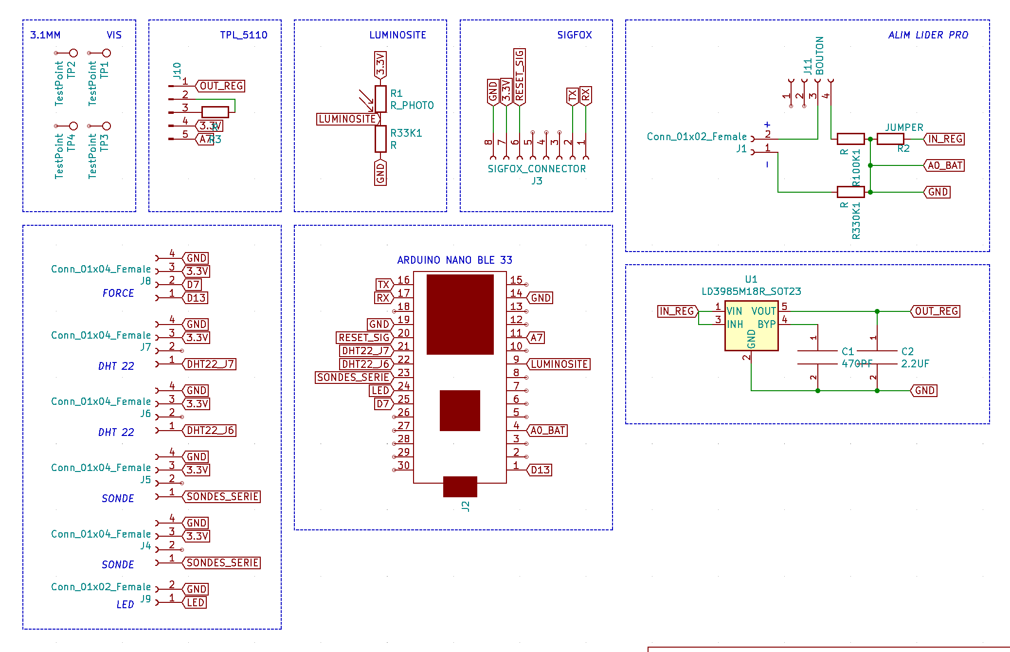
We decided to use the Arduino nano 33 ble board as a microcontroller because it has a large number of GPIO ports, it consumes very little power and it has a Bluetooth module. The fact that it is an Arduino board also facilitates its programming. In order to start programming the board, it is easier to use the Arduino IDE in which we can add different libraries associated with each sensor.
How to use the sensors:Humidity
The first step was to start testing the different sensors one by one, starting with the DH22 sensors. These sensors are measuring humidity and temperature with a precision of ± 0, 5°C for temperature and ± 2 % for humidity. We used 2 of them to measure the temperature/humidity inside and outside the hive. To be able to read the measurements, you need to use simple functions included in the library "DHT.h". With it, it’s possible to carry out measurements according to the desired unit of measurement (Kelvin, Celcius). Each DHT22 requires the use of one digital port.
Temperature
The temperature within a hive is a very good indicator of the health of the bees. Indeed, they self-regulate the internal temperature between 20 and 30°C. That's why we added 2 more temperature sensors DS18B20 inside the hive. The advantage of these sensors is that they are waterproof and they are not likely to be damaged by bees. The other advantage they bring is that the two sensors only require the use of a single digital port on the Arduino. To measure the temperature, you just need to know the identifier of each sensor and define a bus in which you will read the temperature. All the necessary functions are described in the library " MaximWire.h”. However, be careful to define the probes in pull-up mode with the #define MAXIMWIRE_EXTERNAL_PULLUP command. Without this, it will be impossible to measure the temperature. The program that allows you to retrieve the identifiers is available in the attachments of this article.
Weight
Finally, we used a force sensor to measure the weight of the hive. This weight is very important because it will send alerts to the beekeeper. For example, when the hive is stolen which is common nowadays considering the price of a frame filled with honey. It also allows to detect swarming which is the departure of half of the colony of bees that follow the old queen to another apiary. This has a strong impact on honey production. To measure the weight, we used a Wheatstone bridge load cell. Once again, you need to use the functions included in the library "HX711.h". This sensor requires the use of 2 digital ports. We have also fixed a frame around this sensor to support the entire hive. Before using the sensor for its intended purpose, it is necessary to perform a calibration. All the details of this calibration can be found in the Arduino library mentioned above.
Luminosity
We also used a photoresistor that allows us to measure the ambient brightness. It is therefore necessary to make a voltage divider bridge to recover the voltage across the photoresistor. We then connect it to one of the analog ports of the board. The value of the resistor for the bridge divider is important because it will determine the current consumed. It is necessary to take a high resistance compared to the photo resistance so that when the photo resistance decreases, the resistance limits the current and therefore the consumption.
How to send the data:To send our data to a web application, we used a Sigfox antenna to communicate via the LPWAN network. The use of this antenna requires an annual subscription which is not free. It allows among other things the sending of 144 messages per day, each having a maximum size of 12 bytes or 96 bits. The Sigfox payload must respect a certain protocol on which you will easily find all the information. The complicated part is the decoding of the frame on the Sigfox site associated with your card identifier. You have to decode one by one each measurement you have decided to send. To do this, you must specify at which byte the data starts, on how many bits it is encoded, and the number of bits offset from the beginning of the byte. Here is the frame that we decode:
temperature1:0:uint:10 temperature2:1:uint:9::5 temperature3:2:uint:9::4 temperature4:3:uint:9::3 poids:4:uint:10::2 batterie:5:uint:6::0 luminosite:6:uint:20::2 rien:9:uint:8::6 alerte:10:uint:3::6 humidite:10:uint:12::3
We have decided to use Ubidots as a website which is an application where you can collect the data that you send with Sigfox, you can make calculations with them, and display them in an elegant way. It is really easy to use and the API is well documented. However, you can add any IoT hub platform such as Microsoft Azur.
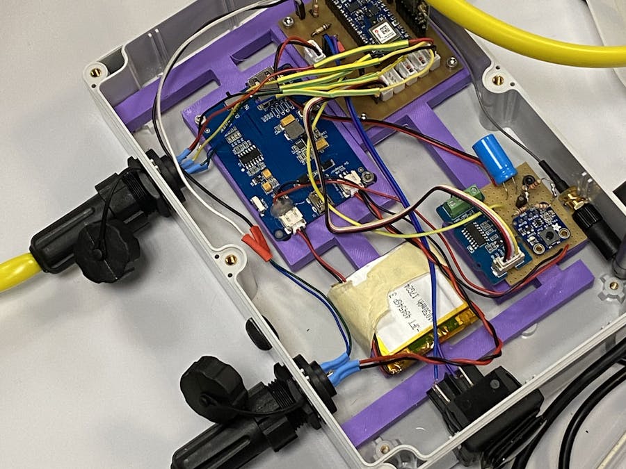
An autonomous system in energy consumption:As you can imagine, our system must be self-powered and durable over time. So, we used a 1050 mAh battery and a 2W solar cell. It is, thanks to the LipoRider Pro, that we were able to convert the energy of the solar panel into power for the battery. At first, we used the 4.2V to 3.3V converter of the Arduino to convert the battery voltage to power the board. But the converter provided in the Arduino consumes a lot. That's why we made our own converter that we integrated into the PCB. To allow this operation, it is nevertheless necessary to cut a gold track on the back of the Arduino board as shown in the following picture. This allows specifying to the Arduino that we do not want to use its own converter anymore. However, it is now impossible to flash code on the board without powering it with 3.3V.
back of the arduino nano 33 ble
In order to limit our consumption as much as possible, we have reduced the consumption of our sensors. It is the weight sensor that was the most energy-consuming. So, our system is self-sufficient in energy and it sends a message every 10 minutes to a website. But we wanted to reduce the power consumption as much as possible during this time. That's why we used a component called TPL5110 which will cut the consumption of any electronic component. To do this, we need to use a resistor of a certain value between the delay pin of the TPL and its ground. This will allow you to define the time during which the tpl will cut the power supply to the board. In order for it to work in this mode, the gold track on the back of the component must be cut as shown below.
In our case, we used a 57kOhms resistor to cut the power consumption of the board for 10 minutes. The 3.3V of the card is then connected to the DRV pin of the TPL which will supply the card until it receives the information on its DONE pin that it can cut the consumption. It is the Arduino that sends this information with one of its GPIO. Then, the TPL cuts the power supply provided by its DRV pin and it reaches the time associated with the connected resistor. The TPL is still powered but does not consume more than 0.6 uAh. With this method, we have reduced our consumption to 0.6 mAh. With this consumption and our battery, the system is autonomous in theory for about 2 months without recharging. In practice, with the weather conditions, it is necessary to have a solar panel to recharge the battery. Nevertheless, during the different test periods, the battery has always remained above 85%.
Warning, if you want to change the value of the resistor to wait more or less time, you have to cut the power supply of the TPL, change the resistor, and then power supply the TPL again. Otherwise, the new delay value will not be taken into account.
UsefullTips:
Before programming the board, you must install all the packages associated with the Arduino nano 33 ble. When you connect for the first time your board, the ide will detect its model and will propose you to install the packages, do it. Moreover, to program the board, you have to check that it is connected to the right COM. This information is available in the Tool -> Port tab.


_3u05Tpwasz.png?auto=compress%2Cformat&w=40&h=40&fit=fillmax&bg=fff&dpr=2)

Comments
Please log in or sign up to comment.