


Hardware components | ||||||
 |
| × | 1 | |||
 |
| × | 1 | |||
 |
| × | 1 | |||
 |
| × | 1 | |||
 |
| × | 1 | |||
 |
| × | 1 | |||
 |
| × | 2 | |||
 |
| × | 2 | |||
 |
| × | 1 | |||
| × | 1 | ||||
 |
| × | 1 | |||
 |
| × | 1 | |||
Software apps and online services | ||||||
 |
| |||||
As our demand for energy continues to grow, we become more and more aware of the efficiency of our homes. The benefits of a more efficient home are easy to see: less energy usage means less cost (whether cost is in terms of money or environmental impact). However, seemingly indirect costs are incurred and tend to get overlooked. We easily forget that, even though we take care to be more energy-efficient individually, we are all in this together.
A simple analogy is fuel economy in your car. Obviously, you're going to get the best mileage on the highway and when no else is on the road. In light traffic, everything flows freely, allowing everyone to maximize their individual efficiency. But when every efficient car is on the road at the same time, traffic slows to a crawl, ruining everyone's fuel economy. The same can be said for air conditioners; no matter how efficient your air conditioner is, if you turn it on at the same time as everyone else, the power grid becomes strained, putting excessive wear on our energy infrastructure.
In fact, Duke Energy (our energy provider here in North Carolina) offers an incentive program to switch your air conditioner off during parts of the day in which demand is highest. One of the obvious drawbacks is that homes can get uncomfortably warm during the day.
But what if you could enjoy the satisfaction of environmental responsibility while mitigating your own suffering in the process? One of the truly powerful aspects of the Internet of Things is the capability to work together with cohesion and intelligence.
Comparison to Existing SystemsThe goal of this project is the same as Duke Energy's Power Manager program; to reduce wear and strain on our energy infrastructure by limiting our most energy-demanding appliance. Unlike the Power Manager program, our project utilizes the Internet of Things to accomplish the same thing while attempting to minimize personal discomfort.
While the Power Manager program switches off your air conditioner without regard to temperature or time since last run, our project will take these factors into account. By taking these factors into account, the homes can communicate with each other, deciding for themselves, the best time to shut down for a while and conserve power. As an added bonus, this system can act as a continuous data logger for later analysis of your home's temperature profile.
The graph below is random sample of logged temperature data and air conditioner run status. The blue line represents when the air condition turns on and the red represents the temperature inside. It's fairly obvious from this graph that it would be best for other air conditioners to run while yours wasn't running anyway.
Rather than concentrate on re-designing something as mundane as a thermostat, we've elected to insert what we're calling an Internet of Things Gate Keeper. This Gate Keeper will decide to allow or block signals from the thermostat, based on input from other Gate Keeper(s). By simplifying the design to a thermostat Gate Keeper, this system can be built entirely using components found in the Particle Photon Maker's Kit.
Temperature Sensing
First, the Photon needs to be able to read the temperature of the house. This is not easily communicated from the thermostat, so it will sense temperature on its own using a DS18B20 temperature sensor (sensor data sheet). The wiring and code for this can be found in the Particle Tutorials.
Thermostat Signaling
In the simplest of terms, a typical residential thermostat is a set of relays that switch a 24VAC signal. This signal is sent down various wires to a control board which handles the more complex switching and timing of the fans. More information can be found here. This Gate Keeper system allows the thermostat to operate normally, but either blocks or allows the 24VAC signal depending on certain criteria.
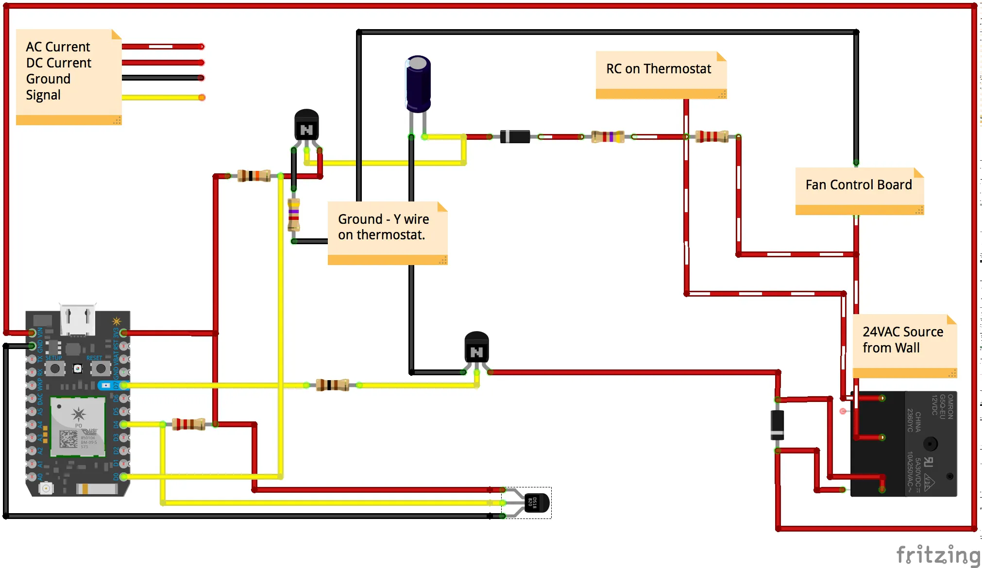
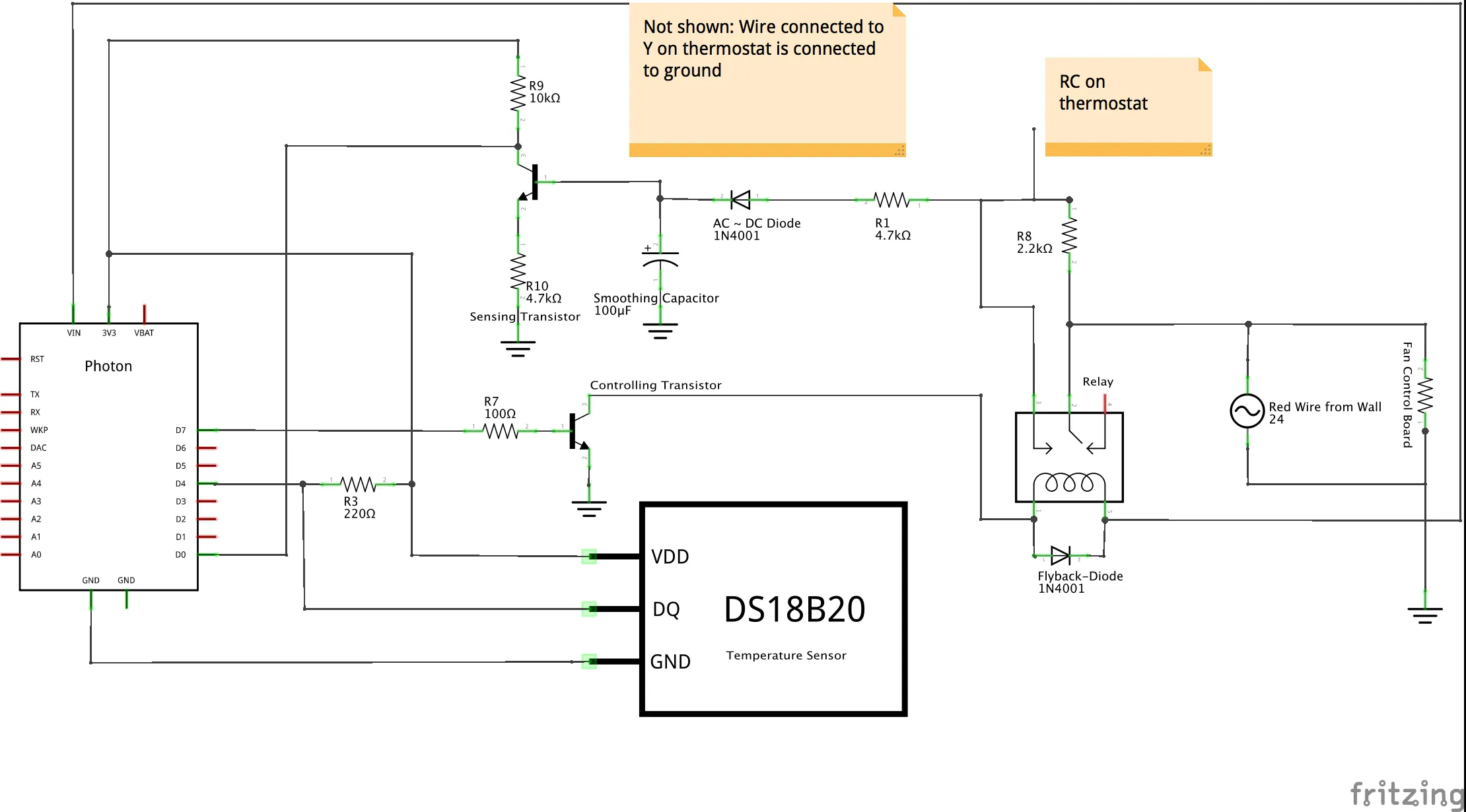
First, we needed to understand when the thermostat wants to make a call to turn the air conditioner on. To do this we looked for a voltage potential between RC and Y on the thermostat terminals. While the thermostat is not calling for cooling, there is a potential of the full signal of 24VAC. When it calls for cooling, that potential drops to zero (like measuring the voltage at two points on the same wire). However, since our Gate Keeper blocks this signal, we needed to let enough current through to give us a useful voltage, but not enough for the control board to initiate cooling. For this, we bypassed our relay with 2.2kΩ resistor, which allowed ~11mA.
This trickle of current was used to activate a NPN transistor which signaled pin D0 on the Particle Photon. Looking at the full schematic, note that there is also a current limiting resistor (R1). Even though the current is only 11mA while sensing, the full current will available to wreak havoc on our hapless circuit once the relay is activated. In this configuration, the Photon uses a pullup circuit to sense the activity of the thermostat as shown in the graphic below.
Thermostat Switching
The 24V signal is blocked by the Gate Keeper so that the thermostat does the switching as if the signal were there. This is done using the relay included with the maker kit. Don't forget the flyback diode to protect your Photon!
How the Code WorksSince the physical wiring allows the photon to sense the thermostat's intentions and control its ability to signal the control board, everything else is done with software. In this section, the two Gate Keepers will be referred to as local and foreign to differentiate between the two members in the system.
The "conversation" between the two members takes place in the Particle cloud. Each member publicly publishes a string of data to which the other subscribes. All of this is done publicly so that there is no need for a single user to claim both members.
Sensing
The sensing signal is sent to pin D0, which is read as a digital signal in the main loop of the program. When the pin is driven high, the boolean variable thermostatCall is set to true and when the pin is driven low, it is set to false. When the thermostat call is initiated (when pin D0 goes from low to high), a system of checks is implemented to decide whether or not it can allow the air conditioner to turn on.
When a call is initiated by the local thermostat, the local Gate Keeper asks the foreign Gate Keeper for permission to turn on (which also means that foreign Gate Keeper needs to be off). This can be interpreted as a series of questions that need to be asked.
Each member periodically uploads a data string that includes temperature, setpoint deviation, call state, run state, priority, request, answer and timer. The data is separated with tildes (which is used as a delimiter when received by the other member). Only some of the data published is actually used by the receiving member (request, answer and deviation).
When a request is made, that member becomes the requesting member and the request bit is changed from 0 to 1. The receiving member uses this to run through a series of if-statements to determine an answer. If the receiving member isn't running or trying to run (no call to turn on is made), then the answer bit is changed from 0 to 1, which the requesting member interprets as a yes.
If the receiving member is running, then it first checks if a thirty-minute timer is running. This timer starts each time the AC begins a cycle. This timer is set for thirty minutes and guarantees a minimum thirty-minute run time for the air conditioner (to prevent rapid cycling).
If the timer is not active, but the receiving member is running the AC, then a setpoint deviation comparison is made. If the receiving member has the greater deviation than the requesting member (more "uncomfortable" than the requesting member), then the request is denied and the answer bit remains 0. If it is the other way around, the answer bit (on the receiving member) is changed from 0 to 1 and the priority bit is changed from 1 to 0 and the AC is turned off. The requesting member receives the answer in the form of a 1 or 0 and then changes its run state accordingly.
If the setpoint is set to 72 degrees F for both members, a typical "conversation" looks like:
32420324_A: 81~9~1~0~0~1~0~0
32420324_E: 75~3~1~1~1~0~0~1
Here, the timer on 32420324_E is active and the request is denied by the seventh bit from the left. 32420324_A will continue to request until it receives approval.
32420324_E: 75~3~1~1~1~0~0~0
32420324_A: 81~9~1~0~0~1~0~0
32420324_E: 75~3~1~1~0~0~1~0
32420324_A: 81~9~1~0~1~0~0~0
32420324_E: 75~3~1~0~0~1~0~0
32420324_A: 81~9~1~1~1~0~0~1
Here, E is running happily, but then A makes a request. Since the timer on E is not running and the setpoint on A is higher, the request is approved and priority is relinquished by E. A receives this approval and takes priority. Because of the order in which the bits are changed in each member, the conversation takes a few iterations. This is done to ensure that both members are not running their respective AC's at the same time.
TestingTo test our setup we connected our circuits up to the our thermostats. This video explains the basics of the system and how one could connect it to their 3M Filtrete 3M22-style thermostat.
Additionally, depending on the type of thermostat that you have this other video shows the connections required for a THT02481 thermostat.
When this project began, our southern summer was still in full force; the days were hot and our ACs were running often. Unfortunately, as time passed, the weather become beautiful and we no longer needed our AC's to run. However, we could still trick our Gate Keepers into thinking they were still running.
In the code, since we used only the magnitude of the setpoint deviation, it didn't matter if our home temperatures were higher or lower than the setpoint. Also, we could simply apply a jumper from 3v3 to D0 on each Photon, tricking them into thinking a call was being made. This allowed us to monitor and track the data to debug the code and show how it works.
To this end, we used If This Then Than (IFTTT) to capture the published data in a spreadsheet and analyze the data. Each member privately publishes both its own data and the data to which it subscribes for data logging and later analysis. These strings are only published when something changes to prevent being inundated with superfluous data.
In the above graph, the run state from each member is logged according to time. Outlined in black are times of code updates (the left side) and internet connection loss (right side).


Comments
Please log in or sign up to comment.