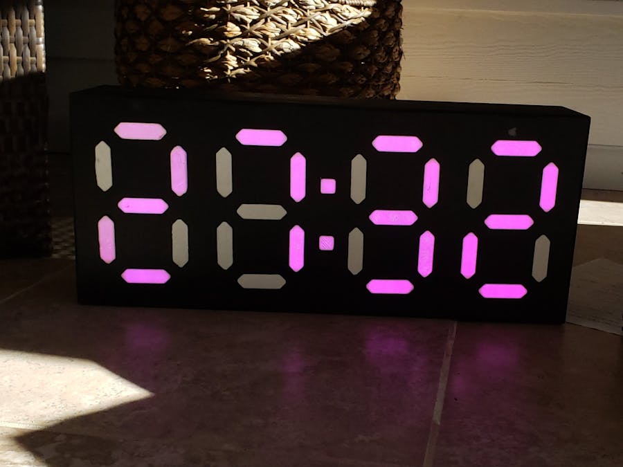
For our IoT project we decided to make a pair of digital pace clocks for the UNC Charlotte Club Swimming Team. The goal for these pace clocks is to have an output that counts minutes and seconds. The display of the clock should be large enough to be clearly read from 25 yards away (length of the pool). The requirements for the IoT part of the project dictated that 2 particle photons must be used each must communicate with each other.
Creating the DisplaysWe looked at a couple options to create the displays. The two main categories for making the output that we considered were analog and digital displays. Because the project outlined that we needed to use particle photons, we decided that an analogue display would make less sense than a digital display. We considered many types of displays, such an LED matrix or a 7-Segment display. Using an LED matrix would give more options as to what can be displayed but at the cost of added complexity. Because these are pace clocks and are designed to only display numbers, a 7-segment display fits the needs of the project the best.
Once we had decided on the 7-segment display, we had to figure out how to make the display. Looking at typical consumer digital pace clocks, we found that most create each segment using a cluster of individual LED’s. These clusters typically have 8-12 LED’s per segment. If we wanted mimic this style of display, each individual LED would need to be soldered together along with resistors for each LED. This would be around 1000 solder joints per clock. Along with all this soldering, each segment would need its own data pin. The micro-controller that we are using, the particle photon, would not have enough pin-outs for each display, meaning that we would also need to use a 7-segment logic board. This would add unnecessary complexity to the project.
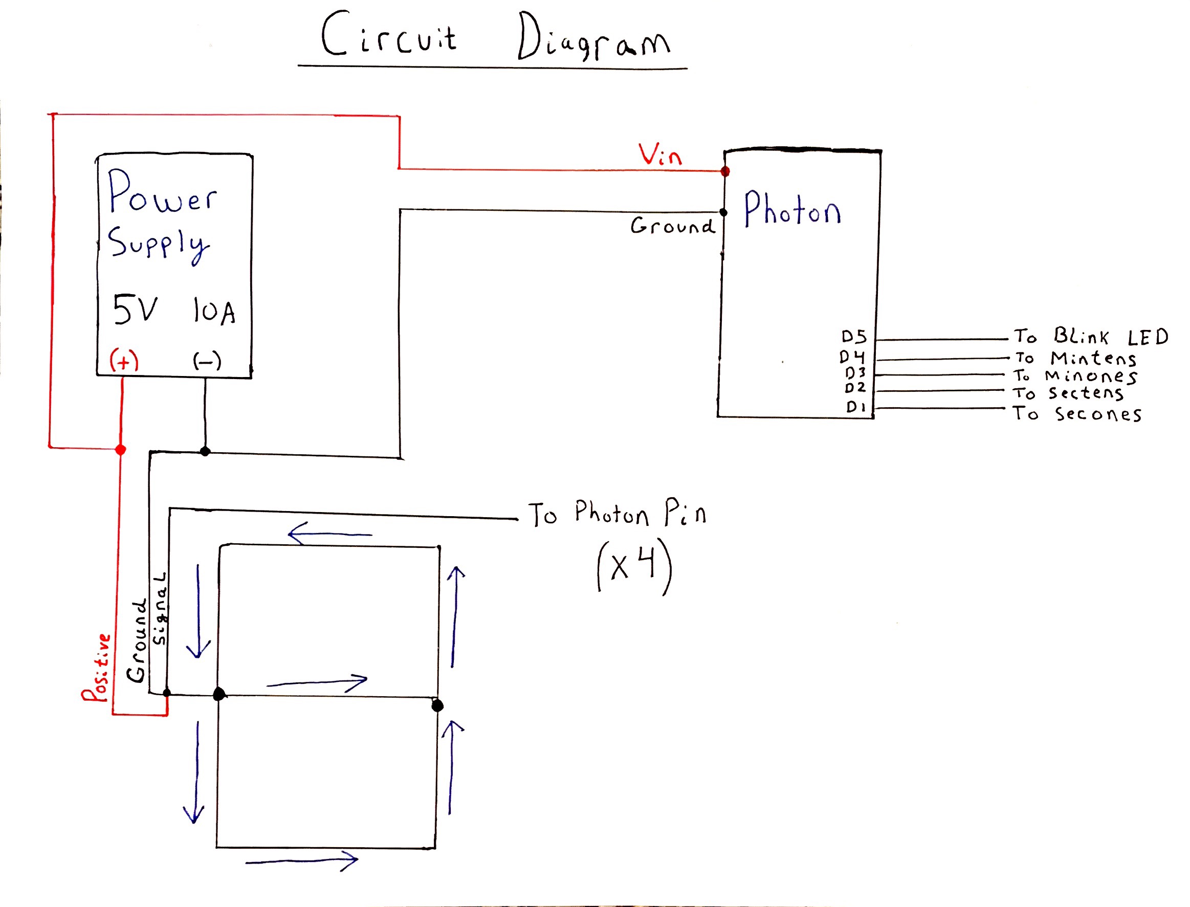
Realizing that making the segments from individual LED’s was not a practical option, we considered what options we had. We found various examples of people making 7-segment displays out of LED light strips. Having no experiences with LED light strips we did some research and found some promising characteristics of the strips. The light strips are cuttable and have pads to make soldering them back into a strip easy. Each LED on the strip is also individually addressable. This means that the light strips can be cut to the length of each segment and arranged to match a 7-segment display. As long as the segments are soldered together to make a continuous line, then each individual LED will be addressable. Upon further reading on 7-segment displays, we found a common wiring convention for this purpose. This is shown below.
Because each segment is soldered together in a line, only one data pin is needed for each digit.
Because we are using particle photons, we had to be selective about what type of LED light strip that we used. Fortunately, the neopixel library is available from the particle web IDE. The neopixel library can control most of the LED light strips on the market today, with the exception of some legacy light strips. We chose the WS2182b strip variety for use in the project. The strips that we purchased were neopixel clones from amazon. We chose to go with the clones to keep the overall cost of the project down.
We used dimensions from consumer pace clocks to figure out the approximate overall dimensions of the clocks and the approximate dimensions of each segment. We settled on a face-plate that is 20 inches long and 8 inches tall. We also determined that each segment should be about 2 inches long and ½ of an inch wide.
Light strips come in a variety of pixel densities, denoted by the number of LED’s, or pixels, per meter. From examples online, it was determined that 60 LED’s per meter would be bright enough for the needs of our clocks. With the 60 LED/m strips, each segment would have 3 LED’s. With the LED's per segment finalized each segment to length and soldered together.
With each segment of the light strip in the right position for the 7-segment display, we needed to make the lights look more like a typical 7-segment display. In order to accomplish this, diffusers were 3-D printed. This allows us to create whatever shape we want for the segments. The CAD models for the segment diffuser is shown below
Along with the 28 segment diffusers for each clock, 2 dot diffusers were also needed. The CAD model for the dot diffuser is shown below.
The thickness of these diffusers matched the thickness of the MDF particle board used to make the body of each of the clocks (0.5 inch). To make the diffusers function properly, precise holes needed to be cut out of the face plate for each of the diffusers to fit into. Because we did not have access to a CNC router, the holes needed to be cut out an old school way.
A template was created using one of the diffusers by placing pieces of wood around the diffuser until there was material surrounding all the edges on the diffuser. The diffuser was taken out and a hole was drilled through the center. This hole was large enough for a ¼” router bit to fit through. The ¼” router bit also had a follower bearing. The ¼” bit was selected because each of the edges have a ¼” radius to them. The bearing on the bit is designed to follow around the edge of the jig created from the diffuser earlier. After following around the entire perimeter of the jig with the router, what is left is a hole that has the same dimensions as the diffuser.
This jig could be used to make all 28 segments for each clock but doing this would require the precise placement of the jig for each segment. Instead another jig was made using the hole cut out from the first jig. This second jig has 7 holes cut in the precise location.
The extra piece of wood at the bottom of the jig is square to each of the segments and allows for the jig to be easily butted up the face plate and have the correct Y-axis location. This means that the only degree of freedom for each digit is in the X-axis. If we had not made this second jig, and used the first jig, then each segment would have had 2 degrees of freedom. Resulting in a lot more time spent measuring and clamping and far more chances for error. With all the holes in the face-plates cut, the boxes could now be glued together. The backs of the boxes were left off and will be screwed together later.
The boxes were then sealed with sanding sealer and coated with bed liner. The sanding sealer step is necessary when coating MDF with bed liner because the MDF end grain is highly absorbent and would not result in a good finish without it.
After the bed liner has dried the segments could be put into the face plate. This required most of the diffusers to be filed down slightly. This is because the diffuser used to make the first jig was unknowingly one of the smallest diffusers of the set. But hey, that’s better than having gaps!
Putting it all togetherWith the diffusers now in place the digits made earlier could be attached to the frame of the clock. This was done by taping each segment of the digit in place and then applying copious amounts of hot glue around each of the segments and wires.
.Using the neopixel library mentioned earlier, the particle photon is able to communicate with the light strips. Both of us having very little experience with coding, we started by figuring out how to get the lights to even turn on. Initially we flashed some of the example code from the neopixel library. This served two purposes: (a) confirmed that the particle photon could control the light strip, and (b) the light strip had no dead pixels. The video below shows the example code running on a light
With the photon communicating with the light strip, we could then begin working on the actual code to display numbers. There are two main ways to go about drawing the numbers.
The first method takes each number and tells what segments to be on and what segments to be off. This would require 10 commands (one for each number) and 7 functions with in each command (one for each digit).
The second method looks at each segment and ties that segment to the numbers that use that segment. This is a far more efficient way to code the digits because there will only be 7 commands (one for each segment) and on function in each command, telling that segment to turn on.
Due to the efficiency of the second method, this logic was chosen to create the function that will draw each digit. This function is called "drawdigit" in our code. With this draw digit function created, the photon is able to take an integer valued 0-9 and output that digit on to the light strip.
To get the clocks to display a time we initially tried to use the millis() command built into the photon. This command starts counting in milliseconds upon start up of the photon. Using some logic, we were able to convert the time in milliseconds into the ones and tens place for both the minutes and seconds. This function would work great for just one clock, but we needed to make 2. The issue that we ran into with this is that the particle photon does not have a very good way of sending this value between devices. After some time spent tinkering with outputting the millis() value, we abandoned this method.
After looking through the particle reference section, we discovered a set of commands called mins() and secs(). These output the current minutes and seconds as integers. These values come from the NIST time server that the particle team has built into the photon library. Using these functions is a much more elegant solution because both photons can call the mins() and secs() command and both will return approximately the same value.
Upon testing the clocks, even with poor connection to the internet, the times displayed never varied more than a second, which is well within the tolerances needed for the pace clocks.
Live Data
https://docs.google.com/spreadsheets/d/1gbqVz1e8U0voMpwqM-cm5AlwdYTNkVQ9dIG9CmlSLUg/edit?usp=sharing
Through the use of If This Then That, we were able to log in google sheets whenever the clocks are synced and running with each other.


Comments
Please log in or sign up to comment.