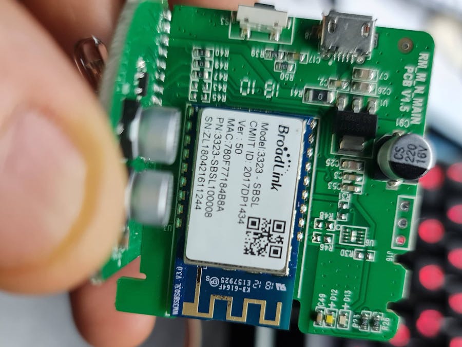
The story is really simple: I bought this RM Mini 3 some years ago. From a day to other it refuse to work, so after opening it and seeing that the module was not an ESP, I put it in a box until some time ago.
Since the module was very similar in appearance to a ESP-12 I had in my drawer for long time, I searched for informations about a possible change.
So I found this rare link https://www.reddit.com/r/broadlink/comments/a6y0q7/pinout_of_the_broadlink_rm_pro_rm3/ to a post where another RM Mini 3 owner shared the hard-hitting informations he retrived. The post mentions this other link https://community.home-assistant.io/t/reverse-engineering-broadlink-rm-pro-devices/85441 and I started from this informations.
I removed, with some problems, the old "brain" uncovering the pads.
First checked the power supply voltages, then the links to the TX and RX pins related to the original pads.
I prepared the ESP module according to the usual minimal schema for its operation, without capacitor. I didn't bother stabilizing and or filtering the power source as it had to be good already.
I connected the various pads to my ESP module (VCC, GND, TX, RX)
Then I connected the GPIO4 and GPIO5 to the pads corresponded to IR SIG (IN) and IR SIG (OUT), according to the schema into the post.
I also connected a wire to GPIO0 ( the little green one) so I could connect it to ground.
At this point I loaded the Tasmota IR version via Tasmotizer with the usual USB-serial converter
After the reset I connected my mobile phone to the wifi network generated by the ESP module and configured the parameters for my home network.
The configuration is very simple with this template {"NAME":"CCXX-IR", "GPIO":[1, 1, 1, 1, 1056, 1088, 1, 1, 1, 1, 1, 1, 1, 1], "FLAG":0, "BASE":18}
The IR IN worked like charm but the IR OUT did not work at all.
I backtraced the input pin to the IR leds to find the schema had an error
I was able to see the original remote control signal JSON strings and send the correct commands to my AC using the Tasmota console.
The MQTT configuration, on the other hand, was not easy because, from what I think I understand from the documentation, the commands should be sent to the topic cmnd/tasmota/gateway_ir/IRHVAC, but this didn't work. Losing a few hours I discovered, looking at the console, that instead the correct topic is tasmota / gateway_ir / cmnd / IRHVAC.
Finally, everything was working correctly.As a final touch I changed the connections of the button originally used as a reset to use it as a programming start. First I removed C17, R50 and R39, connecting the green wire between C17 and R39.
After this I isolated the pin connected to the 3.3V, making a bypass and reconnecting it to the GND
Everything works fine and I haven't had any major problems integrating it into Home Assistant.
At the moment the part concerning the manipulation of the various parameters is missing (temperature, fan speed, turbo,...). I'd like to build a panel in HA with the various commands in order to build the JSON string to send. Suggestions are welcome :-)
Update:
Connecting Gpio14 to the BLUE/WIFI LED pad and updating the template, the blue led shows you the connection status.


Comments
Please log in or sign up to comment.