/******************************************************************************************************
 *                                                                                                    *
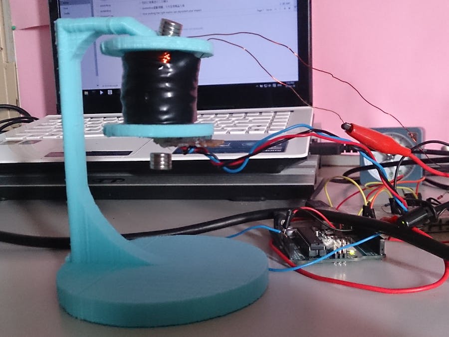
 *                Magnetic levitation program for Arduino Uno/ATMega328                               *
 *                                                                                                    *
 *                                                                                                    *
 *  Copyright (C) 2014 Reid Borsuk (reid.borsuk@live.com)                                             *
 *                                                                                                    *
 *  "MIT Three Clause License"                                                                        *
 *                                                                                                    *
 *  Permission is hereby granted, free of charge, to any person obtaining a copy of this software     *
 *  and associated documentation files (the "Software"), to deal in the Software without restriction, *
 *  including without limitation the rights to use, copy, modify, merge, publish, distribute,         *
 *  sublicense, and/or sell copies of the Software, and to permit persons to whom the Software is     *
 *  furnished to do so, subject to the following conditions:                                          *
 *                                                                                                    *
 *  The above copyright notice and this permission notice shall be included in all copies             *
 *  or substantial portions of the Software.                                                          *
 *                                                                                                    *
 *  THE SOFTWARE IS PROVIDED "AS IS", WITHOUT WARRANTY OF ANY KIND, EXPRESS OR IMPLIED, INCLUDING     *
 *  BUT NOT LIMITED TO THE WARRANTIES OF MERCHANTABILITY, FITNESS FOR A PARTICULAR PURPOSE AND        *
 *  NONINFRINGEMENT. IN NO EVENT SHALL THE AUTHORS OR COPYRIGHT HOLDERS BE LIABLE FOR ANY CLAIM,      *
 *  DAMAGES OR OTHER LIABILITY, WHETHER IN AN ACTION OF CONTRACT, TORT OR OTHERWISE, ARISING FROM,    *
 *  OUT OF OR IN CONNECTION WITH THE SOFTWARE OR THE USE OR OTHER DEALINGS IN THE SOFTWARE.           *
 *                                                                                                    *
 *                                                                                                    *

 *******************************************************************************************************/

//#define QUIETMODE                        //Quietmode slows the time it takes to update the full PWM duty cycle. This makes it take a LOT longer to stabilize (on the order of 30 seconds), but makes almost no audible noise

#define MIN_PWM_VALUE         0          //Minimum PWM duty cycle
#define MAX_PWM_VALUE         255        //Maximum PWM duty cycle
#define IDLE_TIMEOUT_PERIOD   3000       //Milliseconds. Must be < gIdleTime's maximum value
#define MIN_MAG_LIMIT         400        //Trigger point for idle/active mode. If a permanent magnet is in range, hall sensor should read below this value
#define PID_UPDATE_INTERVAL   1          //PWM update interval, in milliseconds. 0 = as fast as possible, likely unstable due to conditional branching & timing interrupts. Must be < gNextSensorReadout's maximum value

#define DEFAULT_TARGET_VALUE  300       //Default target hall effect readout
#define DEFAULT_KP            0.7        //Default Kp, proportional gain parameter
#ifndef QUIETMODE
  #define DEFAULT_KD          1.7
  //Default Kd, derivative gain parameter
  #else //not QUIETMODE
  #define DEFAULT_KD            23.7
#endif //not QUIETMODE

#define DEFAULT_KI            0.0002     //Default Ki, integral gain parameter
#define DEFAULT_MAX_INTEGRAL  5000      //Maximum integral term (limited by signed int below, change to long if > (32,767 - 1024) [1024 because that's the maximum that can be inserted before a constrain operation]

#define KP_INCREMENT          0.1        //Increment used for serial commands (gKp)
#define KD_INCREMENT          0.1        //Increment used for serial commands (gKd)
#define KI_INCREMENT          0.0001     //Increment used for serial commands (gKi)
#define VALUE_INCREMENT       1          //Increment used for serial commands (gTargetValue)

#define FILTERFACTOR 3                   //Weighting factor for hall sensor reading. We calculate a running average, with the most recent reading making up 1/FILTERFACTOR of the average. Lower = faster, higher = smoother

int roundValue(float value)
{
  return (int)(value + 0.5);
}

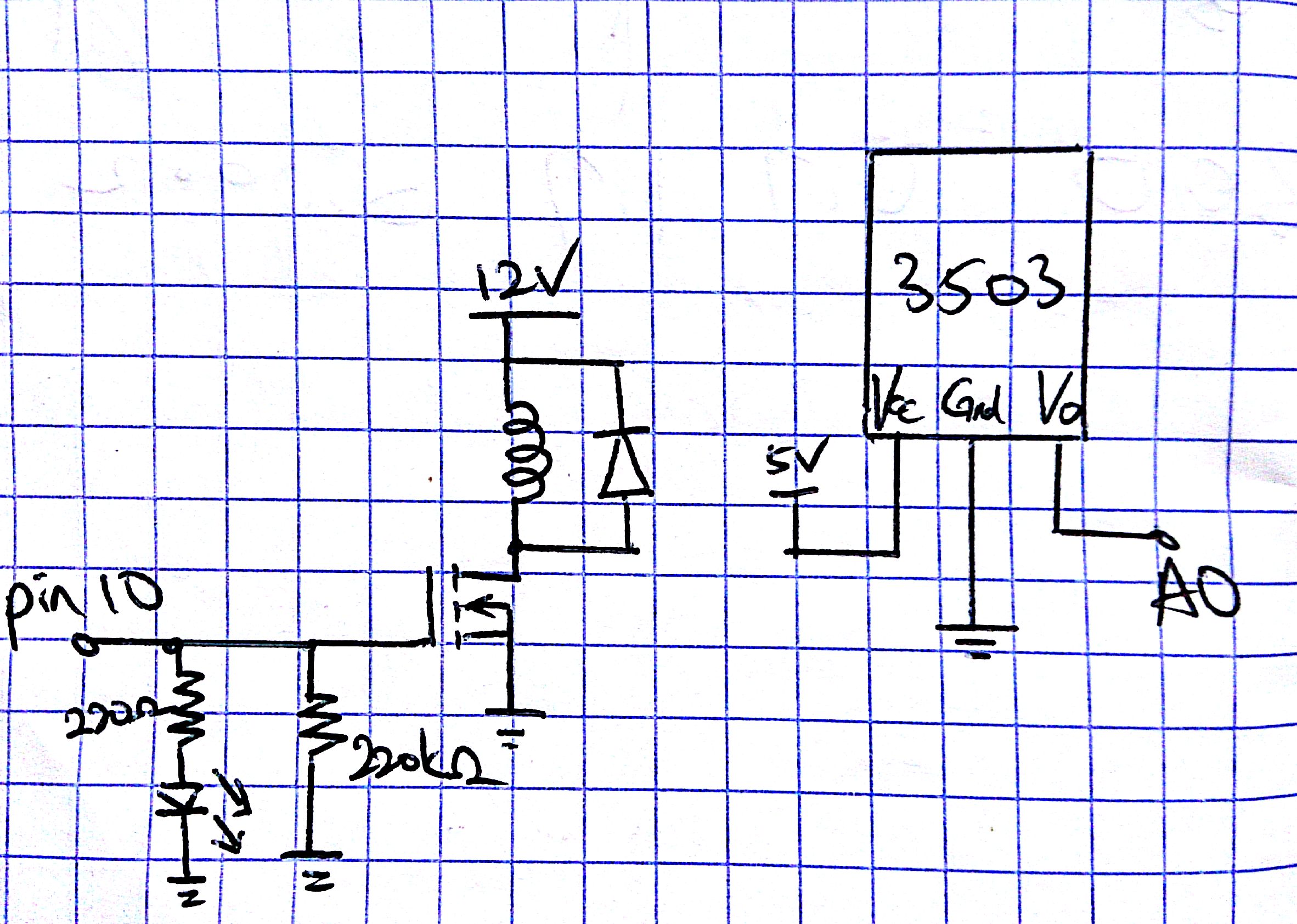
const int coilPin = 10; //Timer 1B on the Uno (ATmega328), Timer 2A on the Mega (ATmega2560)
const int hallSensorPin = 0;
const int redLedPin = 12;
const int blueLedPin = 13; //Onboard LED on Arduino, used mostly to see what the bootloader is doing so we know when we're booted
const int gMidpoint = roundValue((MAX_PWM_VALUE - MIN_PWM_VALUE) / 2); //The midpoint of our PWM range

boolean gIdle = false; //Used to track if we're in idle mode (magnet turned off due to no permanent magnet detected for idle time-out period)
signed int gIdleTime = 0; //KEEP AS SIGNED. Holds the next time we could go into idle mode. Uses overflow safe arithmetic so does not need to hold the entire output of millis(). Must be able to hold IDLE_TIMEOUT_PERIOD without overflow
signed int gNextPIDCycle = 0; ///KEEP AS SIGNED. Holds the next time we need to recalculate PID outputs. Uses overflow safe arithmetic so does not need to hold the entire output of millis(). Must be able to hold PID_UPDATE_INTERVAL without overflow

int gCurrentDutyCycle = 0; //Current PWM duty cycle for the coil
int gLastSensorReadout = 0; //Last sensor readout to calculate derivative term
int gNextSensorReadout = 0; //The "next" sensor value. Declared global so we can use it as a running average and move ot to gLastSensorReadout after PWM calculation

int gTargetValue = DEFAULT_TARGET_VALUE;
float gKp = DEFAULT_KP;
float gKd = DEFAULT_KD;
float gKi = DEFAULT_KI;
int gIntegralError = 0;  //Calculates running error over time

void writeCoilPWM(int value)
{
    OCR1B = value;
}


void setup()
{
    //First thing we set up is the blue LED so we can use it for signaling boot status
    pinMode(blueLedPin, OUTPUT);
    digitalWrite(blueLedPin, HIGH);

    /* Setting up coil PWM settings

     [Only for ATmega 2560]
     timer 0 (controls pin 13, 4);
     timer 1 (controls pin 12, 11);
     timer 2 (controls pin 10, 9);
     timer 3 (controls pin 5, 3, 2);
     timer 4 (controls pin 8, 7, 6);
     [For ATmega328]
     timer 0 (controls pin 5, 6);
     timer 1 (controls pin 9, 10);
     timer 2 (controls pin 1, 3);

     [Timer 1 (ATmega328) or Timer 2 (ATmega2560)]
     prescaler = 1 ---> PWM frequency is 31374 Hz
     prescaler = 2 ---> PWM frequency is 3921 Hz
     prescaler = 3 ---> PWM frequency is 980.3 Hz
     prescaler = 4 ---> PWM frequency is 490.1 Hz (default value)
     prescaler = 5 ---> PWM frequency is 245 Hz
     prescaler = 6 ---> PWM frequency is 122.5 Hz
     prescaler = 6 ---> PWM frequency is 122.5 Hz
    */
    // Setup timer 1 as Phase Correct non-inverted PWM, 31372.55 Hz.
    pinMode(9, OUTPUT);
    pinMode(10, OUTPUT);
    // WGM20 is used for Phase Correct PWM, COM2A1/COM2B1 sets output to non-inverted
    TCCR1A = 0;
    TCCR1A = _BV(COM2A1) | _BV(COM2B1) | _BV(WGM20);
    // PWM frequency is 16MHz/255/2/<prescaler>, prescaler is 1 here by using CS20
    TCCR1B = 0;
    TCCR1B = _BV(CS20);

    pinMode(redLedPin, OUTPUT);
    pinMode(hallSensorPin, INPUT);

    Serial.begin(9600);

    //Boot complete, turn of blue LED
    digitalWrite(blueLedPin, LOW);
}

//Used while in idle mode
void idleLoop()
{
    digitalWrite(redLedPin, HIGH);

    //Turn off magnet
    if(0 != gCurrentDutyCycle)
    {
      gCurrentDutyCycle = 0;
      writeCoilPWM(gCurrentDutyCycle);
    }

    int sensorReadout = analogRead(hallSensorPin);

    //Transition back to active mode if there's a magnet in detection range
    if(MIN_MAG_LIMIT > sensorReadout)
    {
      gIdle = false;
      gNextSensorReadout = sensorReadout; //Prime the sensor readout so it's not super-stale (higher filtering factors will result in longer time to stabilize)
      gLastSensorReadout = sensorReadout; //Reduce the derivative term to 0
      digitalWrite(redLedPin, LOW);

      //This seems pointless, but is used to deal with overflow in millis()'s output when downcast. If it overflows while in idle mode, it would stick in filter waiting for millis to go all the way back up to the last calculated point.
      //Can also set to type's min value to do the same thing, but now is more intuitive.
      gNextPIDCycle = millis();
      gIdleTime = gNextPIDCycle + IDLE_TIMEOUT_PERIOD;
    }
}

//Used while in active mode
void controlLoop()
{
  //Downcast millis to the type of the stored cycle argument, then calculate the difference as a signed number. If negative, the time hasn't passed yet. This allows us to do overflow-safe arithmetic
  if(0 <= ((typeof(gNextPIDCycle))millis() - gNextPIDCycle))
  {
    //By default, downcast to signed 16-bit int (safe), but can be changed to use longer intervals by changing the type of gNextPWMCycle
    gNextPIDCycle = millis() + PID_UPDATE_INTERVAL;

    //Read the sensor at least once in an update cycle
    gNextSensorReadout = roundValue(((gNextSensorReadout * (FILTERFACTOR - 1)) + analogRead(hallSensorPin)) / FILTERFACTOR);


    if(MIN_MAG_LIMIT <= gNextSensorReadout) //We don't see a permanent magnet right now
    {
      if(0 <= ((typeof(gIdleTime))millis() - gIdleTime)) //We haven't seen a permanent magnet in IDLE_TIMEOUT_PERIOD. Overflow safe for the same reason as the above calculation for gNextPWMCycle
      {
        gIdle = true;
        return; //Early exit to fall into idle mode
      }
    }
    else //There is a permanent magnet in range during this update
    {
      //Cast overflow is acceptable here as long as IDLE_TIMEOUT_PERIOD < typeof(gIdleTime)'s maximum value
      gIdleTime = millis() + IDLE_TIMEOUT_PERIOD;
    }

    int error = gTargetValue - gNextSensorReadout; //Difference between current and expected values (for proportional term)

    //Slope of the input over time (for derivative term). This is called Derivative on Measurement, as opposed to the more normal Derivative on Error. Used to reduce "derivative kick" when changing the set point, not a huge deal at our frequency
    int dError = gNextSensorReadout - gLastSensorReadout;

    gIntegralError = constrain(gIntegralError + error, -DEFAULT_MAX_INTEGRAL, DEFAULT_MAX_INTEGRAL); //Roughly constant error over time (for integral term)

    //This is the actual PID magic. See http://en.wikipedia.org/wiki/PID_controller
#ifdef QUIETMODE
    //This slows down the change in the electromagnet, making the device substantially quieter but taking a lot longer to stabilize (on the order of 30 seconds)
    int gNextDutyCycle = gMidpoint - roundValue((gKp*error) - (gKd*dError) + (gKi*gIntegralError));
    gCurrentDutyCycle = roundValue(((gCurrentDutyCycle * 2) + gNextDutyCycle) / 3);
#else //not QUIETMODE
    gCurrentDutyCycle = gMidpoint - roundValue((gKp*error) - (gKd*dError) + (gKi*gIntegralError));
#endif //not QUIETMODE
    //It's possible to overshoot in the above, so constrain to between our max and min
    gCurrentDutyCycle = constrain(gCurrentDutyCycle, MIN_PWM_VALUE, MAX_PWM_VALUE);

    writeCoilPWM(gCurrentDutyCycle);

    //Store for next calculation of dError
    gLastSensorReadout = gNextSensorReadout;
  }
  else //We're waiting for our next PID update cycle, just read the hall sensor for our filtering routine and return. We could also spin on this if we wanted more samples...
  {
    //This is a weighted average function. It basically takes FILTERFACTOR samples, replaces one with the current hall sensor value, and averages over that number of inputs.
    //The higher the FILTERFACTOR, the slower the response (and the less important erroneous readings are)
    gNextSensorReadout = roundValue(((gNextSensorReadout * (FILTERFACTOR - 1)) + analogRead(hallSensorPin)) / FILTERFACTOR);
  }
}

void serialCommand(char command)
{
  char output[255];

  switch(command)
  {
    case 'P':
      gKp += KP_INCREMENT;
      break;
    case 'p':
      gKp -= KP_INCREMENT;
      if(0 > gKp) gKp = 0;
      break;

    case 'D':
      gKd += KD_INCREMENT;
      break;
    case 'd':
      gKd -= KD_INCREMENT;
      if(0 > gKd) gKd = 0;
      break;

    case 'I':
      gKi += KI_INCREMENT;
      break;
    case 'i':
      gKi -= KI_INCREMENT;
      if(0 > gKi) gKi = 0;
      break;

    case 'T':
      gTargetValue += VALUE_INCREMENT;
      break;
    case 't':
      gTargetValue -= VALUE_INCREMENT;
      if(0 > gTargetValue) gTargetValue = 0;
      break;

    //Print current settings. Also printed after any of the above cycles.
    case 'V':
    case 'v':
      break;

    //Ignore unrecognised characters
    default:
      return;
  }

  //Why so complicated? Arduino doesn't include support for %f by default and requires an additional library, so we rip it open manually. Will not support negative numbers or indefinite precision.
  //This one line causes 3026 bytes of ROM to be used, almost half the sketch size...so if you run out of space, disable this (or simplify it).
  sprintf(output, "Target Value: [%3d] Current PWM duty cycle [%3d] Current sensor value [%4d] Kp [%2d.%02d] Kd [%2d.%02d] Ki,Integral Error [.%04d,%d] Idle timeout [%d]\n",
    gTargetValue,
    gCurrentDutyCycle,
    gNextSensorReadout,
    (int)(gKp+0.0001),
    roundValue(gKp*100)%100,
    (int)(gKd+0.0001),
    roundValue(gKd*100)%100,
    roundValue(gKi*10000)%10000,
    gIntegralError,
    gIdleTime);

  Serial.print(output);
}

void loop()
{
    //User commands waiting
    if(0 < Serial.available())
    {
      //Process one character at a time
      serialCommand(Serial.read());
    }

    if(gIdle)
      idleLoop();
    else
      controlLoop();
}
_ztBMuBhMHo.jpg?auto=compress%2Cformat&w=48&h=48&fit=fill&bg=ffffff)


Comments
Please log in or sign up to comment.