Do you have lights and gadgets that plug into a power strip and need to be easily switched on individually? Or frustrated to find the right remote button in the dark to turn on lights. Ever wish to turn simple decorations on your desk into switches?
Here is another way to control your lights and peripherals - with magnets.
I'll demonstrate how I used Infineon 3D magnetic sensors to detect the direction and orientation of magnet to map to light control.
STORY
I have a desk with many decorated LED lights powered from 12V Solar charged battery. I used couple leftover reed switch with a matching magnet from Home security system for a easy quick hookup I find it easier to switch on by sliding the magnets to activate the lights instead of pushing individual switches. I can affix the reed switch under the desk to hide the wires.
When I saw the potential application of using 3D magnetic sensors to detect orientation for more refined control. This can replace couple of reed switches with a single sensor chip.
Advantage
- Customize look and feel of your own switch. Hide inside your decor or 3D printed objects.
- Directional control to quick change to specific combo of switches or color by tactile orientation.
MULTI SWITCH
Instead of individual on/off switch. I used hot zones to program in set of switch controls. For example, turn on speaker that plays music by moving into a specified position on the desk. Or to selectively turn on a fan, radio, and various decor lights without reaching for hardware switches on each device.
There are overlap zones where adjacent switches will be on.
Hardware
The sensor is Infineon XMC1100 XMC2Go which can detect magnets orientation in 3D space.
With magnets' north and south pole in horizontal plane orientation, sensor can detect rotational value calculated based on azimuth and polar coordinates. As well as normal value of magnet from the sensor.
When the magnetic field is within detected threshold normal value, it'll activate the switches. The rotational value will be used to change switch settings.
The control scheme is similar to a rotary switch with push button. Except the z axis has analog value based on magnetic distance and improved accuracy of the heading angle.
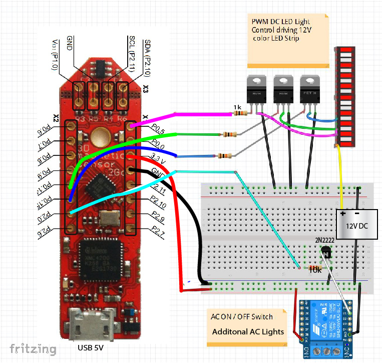
The XMC1100 has 1 PWM to control the white LED light strip.
I mapped the remaining switch position to control colored led lights with preset combinations.
Using the GPIO 4, 5 to control color combination of colored LED strip.
These GPIO can also be assigned to control AC devices using a Relay.
Building the LED Light Switch
The power to the LED Strips are 12V DC. A controller is needed to step up the voltage. I used a transistor to drive the power to the relay.
To control individual LED light, added TIP120 transistor and 1k resistor for each 3.3V GPIO control pin to switch 12V DC
- The firmware is programmed in Arduino using Infineon XMC-for-Arduino
- Follow the instruction in https://github.com/Infineon/XMC-for-Arduino to set up.
- Download the firmware for "XMC1100 XMC 2Go"
Configure the IDE
- Using Arduino IDE, you need to download and add in following link:
File > Preferences > Additional Boards Manager URLs
https://github.com/Infineon/Assets/releases/download/current/package_infineon_index.json
- Install XMC Microcontroller by entering "XMC" in the search box under
Tools > Board > Boards Manager.
- Now add the library to compile the code by following the instruction in
https://github.com/Infineon/TLE493D-3DMagnetic-Sensor
You can now upload the firmware
Program the switch
- Paste in the code "Magnetic Light Switcher" in the code section into the Arduino IDE
Adjust the sensitivity of Trigger distance
This depends on the strength of the magnet you have. LED will light up to activate the lights.
Un-comment the debug info which will print out the coordinates of detected magnetic Normal value. ( remove '//')
//DebugInfo();
Open the serial monitor in Arduino IDE
Test to obtain the values and distance you want to activate the lights. Change the Proximity threshold value.
float PROXIMITY = 1.5;
Configure switch trigger zone
You can set the parameters for GPIO switch pin number, start and end range of the switches activation angle in degrees.
 SwitchOnAngleRange(SW2_PIN, 180, 270);
 SwitchOnAngleRange(SW3_PIN, 260, 350);
Activate both switches by overlapping the end angle of 1st switch with start angle of adjacent switch.
Conclusion
Using Infineon 3D Magnetic sensor as a switch is a novel and fun way to turn on gadgets with preset settings based on orientation. Though similar set up could be done with traditional reed switch and a potentiometer knob, the small magnetic sensor provides add function and flexibility for easy customization.


Comments
Please log in or sign up to comment.