


Hardware components | ||||||
 |
| × | 1 | |||
| × | 1 | ||||
| × | 1 | ||||
 |
| × | 1 | |||
Software apps and online services | ||||||
 |
| |||||
| ||||||
Hand tools and fabrication machines | ||||||
 |
| |||||
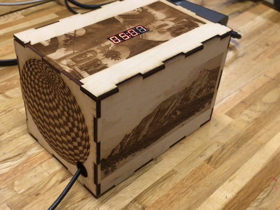
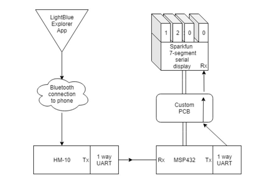
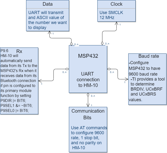
Our goal was to design an embedded system that connects to our phone via Bluetooth and controls a 7-segment display that displays real time. To accomplish this, we used the DSD TECH HM-10 module to establish a Bluetooth connection between a phone and the MSP432 so that we could input the time to initialize our clock. We designed a custom PCB to act as a shield, connecting the Sparkfun 7-segment serial display to the MSP432. The MSP432 communicates with the two peripherals through the UART communication protocol.
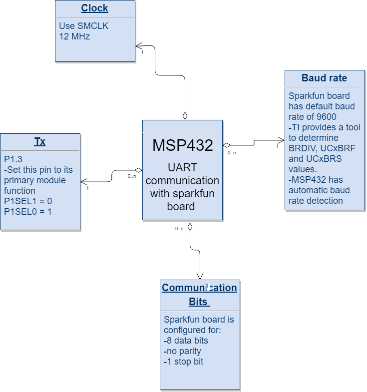
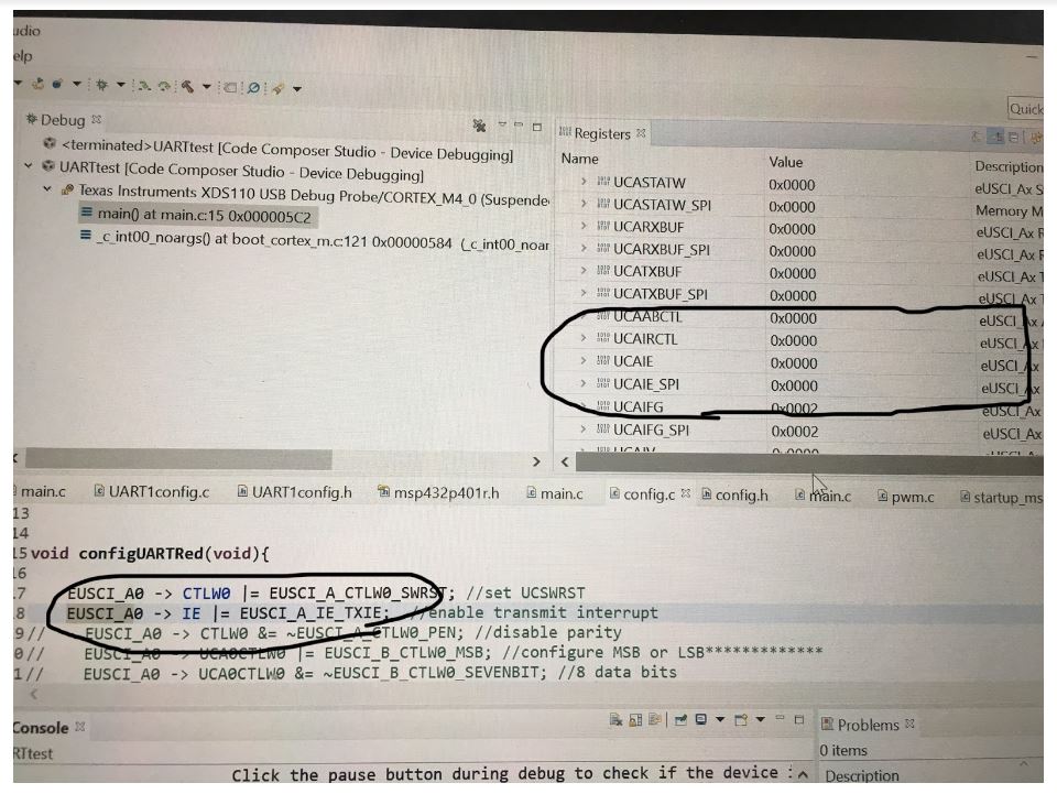
One of the most important steps in creating our project was configuring the MSP432 to communicate with the two peripherals through UART. We accomplished this using the MSP432's technical reference manual which provided a somewhat step-by-step method of configuring the necessary registers on the board. We configured the MSP432 to communicate using a baud rate of 9600, sending the least significant bit first, with no parity and one stop bit. Both of the peripherals have a default baud rate of 9600.
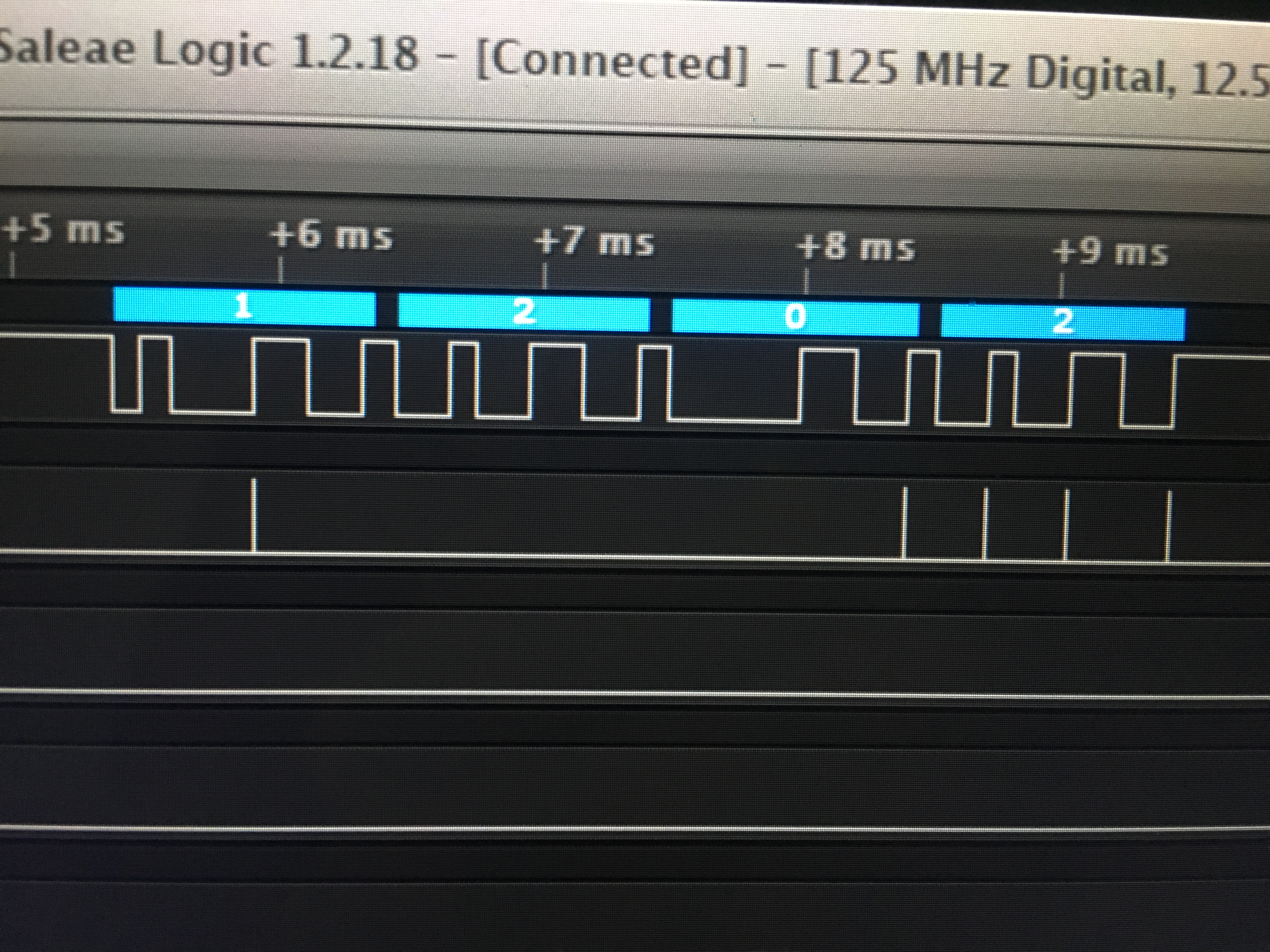
When data is sent to the HM-10 Bluetooth board from our phone using the Lightblue explorer app, it is automatically sent out of the TX pin and is received at a RX pin on the MSP432. This data then goes into the RX buffer and an interrupt flag is raised to show that there is a byte of data in the buffer. Whenever this flag is raised, we store the data in the buffer in an 8 bit integer. We repeat this process 4 times to send each digit of the current time. Then, when all the data has been received, we use bit shifting and concatenation to turn the four 8 bit values into two BCD values which represent the current hour and minute. These BCD values are then stored in registers of the RTC (real time clock) peripheral of the MSP432 which keeps time based on our initialization values using a 1 Hz clock it creates using prescale dividers based on the frequency of the clock we use to configure the RTC. Once the time is stored in the RTC, it is updated at 1 Hz frequency, meaning that if we initialize the RTC to the correct time, it will continue to be accurate. This RTC data can then be read into two 8 bit integers which we split into the four numbers that are sent to the sparkfun 7-segment display board. To send data, we first wait for an interrupt flag to go high meaning that the buffer is empty and then set the TX buffer on the MSP432 equal to each of these data values, one at a time. Once the sparkfun board receives the fourth value, it begins displaying the time. To consistently update the time on the display, we use a while loop that continuously sends the four data values we pull from the RTC.
Project Scope
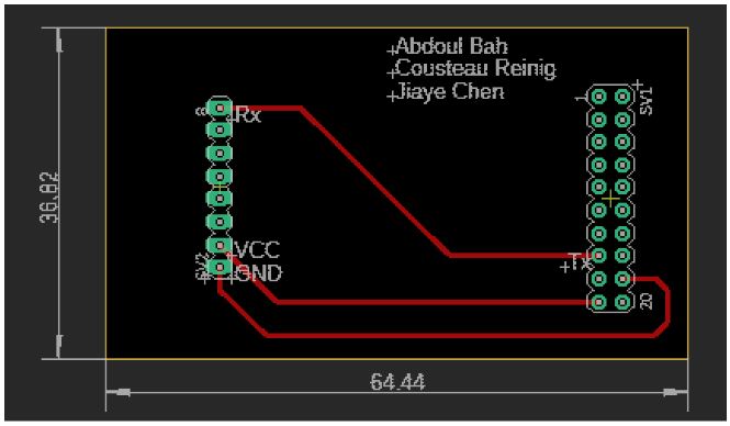
We used the MSP432 with real time clock input from the HM-10 to drive the Sparkfun 7-segment serial display using the UART communication protocol for both connections. Our components include a custom PCB which we designed to connect to the pins of the MSP432 on one side and the pins of the Sparkfun board on the other side. While the PCB attaches to 20 of the pins on the MSP432, only 3 of these pins connect to pins on the Sparkfun board through traces. The 3 traces connect to VCC, ground and the Tx pin of the MSP432. As a result, we connect the two boards without using wires. The communication between the Sparkfun board and MSP432 is mono-directional because the sparkfun board does not transmit data.
We configure P3.3(PM_UCA2TXD) on MSP432 and RX(PD0) on Sparkfun board for this communication. The communication between HM-10 and MSP432 is also mono-directional. We configure P9.6(UCA3RXD) on MSP432 and P1_6(UART_TX) on HM-10 for this communication. Our real time clock input comes from a Bluetooth signal between the HM-10 and the LightBlue Explorer App. The MSP432 transmits data to the Sparkfun board through the PCB as hexadecimal values. The registers of the real time clock generate BCD data which we separate into bytes that represent individual digits of the time.
Project Requirements
For this project, we are required to use the MSP432, the UART communication protocol and create a custom PCB to physically connect a peripheral board to the MSP432. We are also required to have an input, which we decided should input an accurate clock so that our clock can be synchronized. This input comes from the HM-10 board which gets an accurate clock using a Bluetooth connection to a phone. We use UART to communicate between the MSP432 and both peripherals. As we developed our project, we used the debugger as well as a logic analyzer to verify that our circuit was behaving properly and to troubleshoot problems when it was not behaving properly. As we worked on the project, it was helpful to commit our code to GitHub making it easier to remotely collaborate.

Logic analyzer debugging of UART communication
Using the MSP432 debugger


_t9PF3orMPd.png?auto=compress%2Cformat&w=40&h=40&fit=fillmax&bg=fff&dpr=2)


_3u05Tpwasz.png?auto=compress%2Cformat&w=40&h=40&fit=fillmax&bg=fff&dpr=2)

Comments
Please log in or sign up to comment.