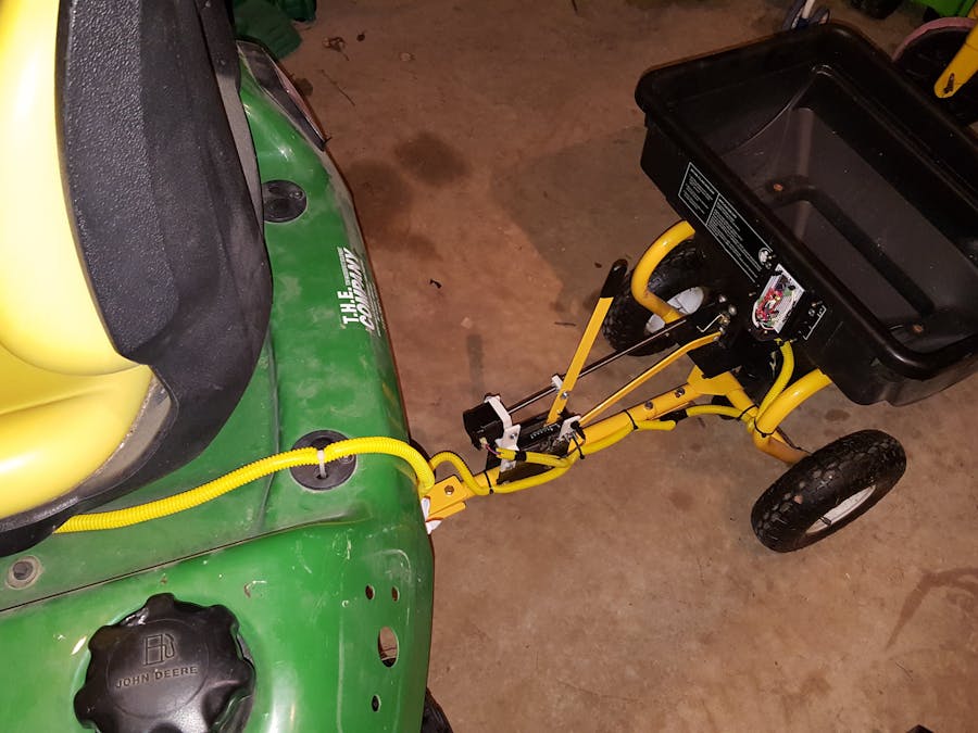
One day I fertilizing my yard and thinking about what my next project should be. After about an hour of trying to get the rate set correctly on the fertilizer spreader, and uncomfortably reaching behind me to turn it on and off manually I decided there had to be an easier way.
So I decided to automate the process with an Arduino and a stepper motor. Check out the video below. Now all I have to do is press a button to turn it on and off, and use a knob to adjust the rate.
How does it work?Mechanical Components
The stock adjustment on the fertilizer spreader utilized a spring and adjustment stop to set the rate. I removed the spring and adjustment stop to allow the handle to move freely.
The stepper motor, screw, and screw nut came as a kit from Amazon. I think it was a replacement kit for a 3-D printer. I designed and 3-D printed a mount that allows the motor to pivot as the handle moves back and fourth. I included .step and .stl files of the parts on Github if your'e interested. I used heat set threaded inserts to attach all the parts.
Electrical Components
I used an Arduino Nano and an Easy Driver from Sparkfun to control the stepper motor. For the electrical schematic please see the frizting diagram at the bottom of the page. I choose to use full steps for the stepper motor. I wanted the highest torque and did not necessarily care that much about precision.
However this driver does allow you to do 1/2, 1/4, and 1/8 steps if you need more precision. Sparkfun has a great write-up on stepper motors here https://learn.sparkfun.com/tutorials/easy-driver-hook-up-guide
To stop the lever when the flow control gate is fully shut I used a magnetic reed proximity switch. For the controls I used an on/off switch to open and close the flow gate, and a standard potentiometer to control the opening position of the flow gate.
The only other thing I have on the perf board is a 5vdc voltage regulator for the Nano. The power coming from the lawn mower is 12vdc.
Enclosure/Hanesses
Since fertilizer is very corrosive it was important to make sure everything was sealed and protected.
To house the electronics I used a Circuit Armour Perfbox. It is an enclosure I designed and am now selling on Tindie if you are interested https://www.tindie.com/stores/cachen/. There are two versions, one that holds a half sized breadboard and one that holds an Adafruit half sized perf board. In this project I used a perf board since it is going to be bouncing around on the spreader. I just soldered the components on the perf board and slid it in the enclosure.
I used 20ga wire to run to the stepper motor and sensors and covered it with corrugated tubing to protect it. I used a Molex MX150L sealed connector between the lawn mower and spreader. This way I can easily disconnect it.
I also sealed the stepper motor connector with silicone and put tape over the back of the stepper motor since the shaft was exposed.
My lawn mower has a 12vdc cigarette outlet so I used that for power.
Software
The software is fairly straight forward. I used digital outputs to control the set-up pins on the stepper driver. The on/off button and proximity sensors use digital in pins and the potentiometer to control the rate uses an analog in.
To control the speed of the stepper motor i used a PWM pin. As you vary the output of the PWM pin between 0 and 255 the stepper motor will speed up and slow down. Each pulse is one step of the stepper motor (in full step mode). Using the PWM output works for this application because position accuracy is not critical. If you had an application where you needed to know exactly where the motor was positioned at all times you would want to use a different method, where you could count the pulses.
When the electronics first power up it runs the home subroutine which turns the motor to shut the flow gate until the proximity switch is tripped. Then it checks to see if the conditions are right for calibration mode.
Calibration mode will let you set the maximum open position (maximum rate). If the on/off button is on and the pot is at max when the electronics power on, it will go into calibration mode. This means it will open the gate until the on/off button is turned off. At that point it will take how many milliseconds it took to open the gate and save it to EEPROM.
After the set-up is complete it goes into the main loop, which monitors the on/off button and potentiometer for changes in state. If a state change is observed it calls a subroutine to turn the motor. I send the amount of time I want the motor to run and which direction to the subroutine. The motor run time is determined by using the time it takes to fully open the flow gate (set in the calibration routine) and the potentiometer position.
One other thing I learned during this project, is that whenever you're not turning the stepper motor disable the stepper driver. At first I was leaving it enabled all the time. But the stepper driver chip was getting super hot, because current was passing through it all the time, to lock the motor in place. So if you aren't turning the motor disable it using the enable pin on the stepper driver.
The code is attached with comments.


_3u05Tpwasz.png?auto=compress%2Cformat&w=40&h=40&fit=fillmax&bg=fff&dpr=2)
Comments