


Hardware components | ||||||
| × | 1 | ||||
 |
| × | 1 | |||
 |
| × | 1 | |||
 |
| × | 1 | |||
Software apps and online services | ||||||
 |
| |||||
| ||||||
 |
| |||||
Forest fires have become a growing concern in recent decades due to their increasing frequency and intensity. These fires can be devastating, affecting not only ecosystems but also human settlements, air quality, and global climate patterns. As climate change accelerates and human activities encroach further into wildlands, understanding and improving forest fire detection has become crucial.
Forest fires account for significant environmental and economic damage. In the United States alone, forest fires burn millions of acres each year, with recent statistics showing that the 2020 wildfire season was one of the most destructive on record, consuming over 10 million acres of land. Similarly, in Australia, the 2019-2020 "Black Summer" fires were catastrophic, burning over 18 million hectares and causing profound impacts on biodiversity and human health.
The European Union also faces substantial fire risks, with Mediterranean countries experiencing severe fire seasons that threaten natural habitats and agricultural lands. Countries like Brazil and Canada are not exempt from these challenges, with the Amazon rainforest and Canadian boreal forests facing increased fire risks that have significant global implications for carbon sequestration and biodiversity.
The importance of effective forest fire detection systems cannot be overstated. Advanced technologies, including satellite monitoring, remote sensing, and artificial intelligence, are being employed to detect fires early and improve response strategies. These innovations offer the potential to mitigate the impacts of forest fires and enhance our ability to manage and protect valuable forest ecosystems.
This introduction provides a foundation for exploring the critical role of forest fire detection systems in the context of global fire statistics. By examining the patterns and impacts of forest fires worldwide, we can better appreciate the need for robust detection methods and their role in safeguarding both natural and human communities from the ravages of these increasingly frequent and severe events.
MAIN DIAGRAMAll of the process of this project is described with main application diagram below. AMD PC AI will be act as main executor to collect all data from Environment Sensor BME680, capturing forest fire image with usb camera and perform image detection. AMD PC AI will send all collected data to the cloud server, and End Users can read the data real time view the detection image using simple GUI.
Forest fire data (environment sensor and image processing result) will be collected periodically (every one minute). AMD PC AI will request the sensor measurement value (Temperature, Humidity, Gas) to the sensor device, and it will send feedback to AMD PC AI in formatted data. At the same time AMD PC AI will capture the latest image from forest fire, then doing the AI inference for captured image. If there is fire and smoke detected in the image, it will send data with image included in the Data Payload. Later then the End Users can load the image from GUI to view latest detection for verification.
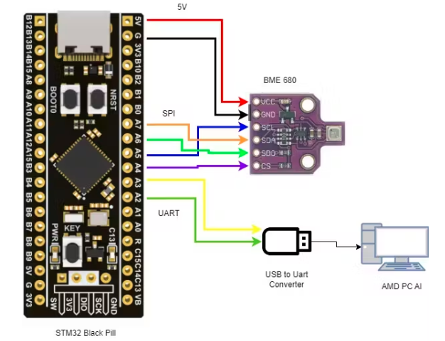
HARDWARE PREPARATIONBeside AMD PC AI, there are co-hardware to help PC AI perform the forest fire monitoring. As described in Main Diagram, the co-hardware is USB Web camera and Environment Sensor. USB Camera can be attached directly using it's USB cable to PC, but the Environment sensor need microcontroller to support the sensor measurement. Hardware diagram and schematic are shown on below figures.
The co-hardware utilize STM32 Black pill for harvesting sensor data measurement from BME680 environment sensor. Black pill board using SPI interface to perform data acquisition from BME680 and store data return from sensor in internal memory device. Black pill will construct sensor data format and send all the sensor value in formatted data through UART to AMD PC AI, thus USB to UART conversion needed to support the data transmission.
Based on diagram, connection for Co-Hardware:
To wire all of the components onto one solid board, it needs brakout-board or pre-drilled PCB and made the connection by soldering the wire according to the connection table. The results of connection are shown in figures below:
It needs small box enclosure to cover up all the connection cable. The connections are made through PCB from AMD PC AI to environment sensor. The board is powered by 5V from the USB PC. The webcam cable also routed inside the box enclosure to avoid messy wiring.
AMD PC AI ENVIRONMENTBefore performing image processing, the AMD PC AI need to be configured properly in order to perform the inference using its IPU. So Installing the required software and driver need to be executed. Refer to the AMD Document reference for the complete installation guide to enable the NPU/IPU driver in Windows environment. To test whether it is successfully installed, it needs to run one of the example provided. In this project, since we are going to utilize YOLOV8, it can use the YoloV8 example to test out the inference performance. From this picture below, it is successfully installed NPU driver and leverage it into Conda Virtual environment.
This project does not utilize native conda tools python interface programming like jupyter notebook. instead of using Jupyter Notebook, this project using Pycharm as the IDE/Python Compiler interface. Inside Pycharm it can run on Conda Virtual environment that already created where the NPU driver is installed. To run the test, we can excute the command ".\run.bat --e2e --vai-ep --img..\..\test.jpg --voe-path <path to voe package>". The result whether our environment is ready or not, can refer to this example result:
The result shows that the inference is run on IPU hardware, where the utilization of IPU is 97.80% and it using VitisAIExecutionProvider to perform the inference from example image.
DATASET and MODEL TRAININGSince the AMD PC AI will need to perform custom object detection, it need custom trained model to do the inference. To obtain this, the data training need custom dataset that reflect the forest fire and with label on the image. Labeling the image for model training required much effort by labeling 8K or more images. That is why the data preparation needs amount 50-60% of the Effort in process of object detection with AI.
To overcome this efforts, custom dataset can be downloaded instantly from Roboflow, so this project can proceed faster to data training directly without collecting image from Google and doing the manual labeling.
this project utilize the custom dataset for forest fire detection, can be downloaded here. The accuracy of datasets is quite promising by 83% of precision. It can also testing out the inference by uploading our example image. the result can be shown below, where smoke and fire detection reach 77% and 83% confidence accordingly.
We can also downloaded dataset in other format for data training such as YoloV8 Format, TF Record or coco dataset format.
Model training for yolo V8 required high performance GPU, suing CPU for training required much time and it not suitable for custom model training. The model training for this project is trained using Google Colab, example code can be copied here:
Training with 150 Epoch requires 12 Hours using T4 Google GPU, Instantly the pre trained YoloV8 model can be downloaded directly from this project Github repository.
To test the inference, native YoloV8 Python API command is used to perform the inference. Inference test result from trained model is shown in picture below, where the inference detect smoke and fire 73% and 79% confidence accordingly for example image. The result is quite promising for forest fire detection in realtime using usb camera.
Workflow of BME 680 Measurement process is fully described in below diagram. The firmware need to start by initialize the SPI interface for Black pill board, and then initialize its UART interface. As described in the schematic, Black Pill and BME 680 Sensor is communicating via SPI interface. Black pill will sue the command to read sensor value and arrange them into data payload.
After acquiring the environment data, Black pill will utilize it UART interface to send the data to AMD PC AI. For debug purpose, some of header are enabled to check the data and flow. Result of firmware development is shown on figure below:
To order the co-hardware to start the measurement, AMD AI PC need to send "START" command, indicating that Black pill will need to request measurement process to BME680. The Arduino Config need to be set properly in order the Black Pill working as expected. Full firmware code can be download here
FOREST FIRE GUIRealtime status of forestfire monitoring can be viewed by using simple GUI. This GUI using MQTT as server to exchange data between End Users and AMD PC AI and able to load image detection result in image format and view it through GUI. This GUI will update it's data once received new data inside MQTT payload. The GUI will split the data according the information that received from AMD PC AI.
AMD PC AI will need to send data in JSON format, described in code below:
payload = {
    "temperature": temperature measurement data (in float),
    "humidity": humidity measurement data (in float),
    "gas": gas measurement data (in float),
    "image_available": True or False,
    "image_data": base64_image data format
}
Below picture is the GUI for Forest Fire detection, where it shows mqtt connection status, environment sensor value, and image detection. The indication where image available is image_available : True. If this value is true, then image can be loaded into GUI.
Function of the GUI Buttons:
Start MQTT Server -> to start MQTT Server on Localhost (can be modified if deployed to online server)
start -> Connect mqtt client to mqtt server by subscribe to particular MQTT Topic
stop -> Stop MQTT Connection
Load Image -> load image detection to GUI (if image_available == True)
Complete GUI Implementation code can be downloaded here:
DEVICE TESTMain Program Flow Diagram:
The main flow of forest fire detection program is started from initializing the camera and capturing the realtime images. Once AMD AI PC got the image, the code will start the inference on detected image and draw the bounding-box with confidence on the images.
The AMD AI PC will continue to get environment data from co-hardware by sending request command. Once it get all environment data, AMD AI PC will combine all data into one json formatted payload.
Once it get all data, the AI PC will start to connect to MQTT server and subscribe to specific topic, and load the topic with payload data. So the GUI can receive the payload and showing it to END-USER.
Device test process is by simulating or providing the camera the image of forest fire shown in below picture, where in this test, image are loaded through phone and then captured by the AMD AI PC Camera, and doing the inference for captured images.
We don't want to start the actual forest fire to validate the functionality, thus forest fire simulation is sufficient to do the validation. Note that the camera position need a good adjustment to have good captured picture
Result of image detection is shown in image below, where AMD AI PC are able to do fire detection on the captured image that simulated from the phone. The result also show that the inference result is good enough under low light image capture.
Inferencing run-time for fire image detection recorded as less than 1 second, showing in picture below. For whole process start from capturing the image, acquire the sensor data, and send the payload to MQTT server requires less than 10 second. Which is more than enough to do real-time monitoring of forest fire.
Front View. The camera with support board are glued on the top of MINI PC, shown on figure below. Support-board are combined together with camera and glued to the cop case of AMD AI PC. The wiring of camera and environment sensor are covered inside box enclosure.
Top View. From the top, the support board are covered with transparent enclosure but the environment sensor need to be exposed to outer board so it can measure the environment condition properly. Wiring inside box is covered through transparent cap, enable user to view the hardware status and condition.
Back view showing the connection from Support-Board to AMD AI PC. As mentioned in the hardware diagram, the USB - Uart converter is connected to dedicated usb ports as well as camera usb connector.
Side view to give user another point of view to have a good hardware assembly.
Demonstration Video
Hardware Introduction
Hardware test and simulation
MISCYoloV8 to ONNX model Conversion and Vitis-AI Quantization
As described in this Documents, pretrained model using custom datasets need to be converted into ONNX model and then Quantized using Vitis-AI ONNX Quantizer tools. In this project, Model Conversion from YoloV8 to ONNX has been done by using YoloV8 export command to ONNX model, and The ONNX model also quantized into Vitis-AI model using Vitis-AI tools, been done in this experimental code. This experiment able to generate ONNX model and ONNX quantized mode, stored in this directory.
Inference test between model conversion showing unexpected result, where the detection result between yolov8 model is different compare to ONNX conversion model and Vitis-AI quantized model, showed in below pictures.
YoloV8 model inference results:
ONNX model inference results:
ONNX Vitis-AI quantized model inference result:
From the log file shows that the model have additional layer input after ONNX to Vitis-AI model quantizing process, thus the tools is getting confuse when doing inference and throwing errors message.
Further Investigation showing that the Model conversion result from YoloV8 to ONNX is not behaving as expectation. From ONNX model visualization showing that the input image/tensor is 1*3*640*640 where the expected input should be 640*640*4
After quantization, since the generation method utilize the image size to do conversion, showing that the tools trying to create another input which equal to image size. Due to this misbehaving, the result of inference can't be visualized. Image below showing the quantization model that have two input, which throwing error messages on the inference tests.
Full discussion with AMD Engineer can be followed here. They suggest to utilize Vitis-AI build-up YoloV8 to do the training. But due to limited hardware and tools, the training could not be completed. Alternative tools approach to train model such Tensorflow and Pytorch has been tried but another issue gate the development process.
REFERENCES1. https://github.com/amd/RyzenAI-SW/blob/main/tutorial/yolov8_e2e/code/examples/tutorial.ipynb
2. https://github.com/Xilinx/Vitis-AI-Tutorials/blob/1.4/Design_Tutorials/08-tf2_flow/README.md
3. https://github.com/microsoft/onnxruntime/issues/16638
4. https://pytorch.org/tutorials/advanced/super_resolution_with_onnxruntime.html
5. https://universe.roboflow.com/dongguk-nr7gx/forest-fire-detection-lucg0/model/2
6. https://ryzenai.docs.amd.com/en/latest/vai_quant/vai_q_onnx.html


Comments
Please log in or sign up to comment.