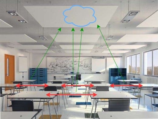
The recent variant of Covid-19, Delta, has spread around the globe, causing new wave in several country. Still the best prevention of this newly variant is by using medical-mask, staying at home, and create the safety spaces.
In this project will be introduced the monitoring system for public spaces (e.g Office) using BLE from ESP32. The RSSI data from BLE client/Broadcaster will be exctracted, and then calculated using some formula to get the distance value. The distance between BLE (Broadcaster - Observer) will be converted to the coordinate using triangulation formula. Finally, by knowing the coordinate, we are able to detect the distance between broadcaster (client).
The system illustration is shown in fig 1, where the system using 3 nodes as observers, and some of broadcasters (clients). The clients will broadcast its BLE properties (UID, ID, RSSI, Service, etc) to all of the nodes. The nodes will scan all of the broadcasters, get the RSSI value, then prepare the data payload for the AWS cloud. Once the node got RSSI, it will send directly to MQTT Server at AWS Cloud via existing WIFI access point. At the access point, beside the nodes, the monitoring at local computer also connected to AWS cloud to sniff all of received data at MQTT server/AWS Cloud. The Monitoring will be working as data processing, where all conversion from RSSI to Coordinate/Distance happens. To read more about RSSI Calculation, I wrote it in my previous blog at distance detector.
HardwareThe Hardware will be divided into two parts, those are the nodes and the clients. The nodes are using ESP32 (M5Stack core2 + 2 additional ESP32) and the clients using smartphones with BLE. So, the number clients might be unlimited, but since its for a healthy space, the amount of clients will be limited automatically.
Some figure from the project.
The client is a smartphone that support BLE. It can use BLE simulator application in Google Play Store to run broadcasting mode. Illustration of the room condition in 2D is shown in figure 10.
The position of clients will be represented in cartesian coordinate (x, y).
SoftwareThe software/firmware for the nodes is developed under Arduino IDE with some of compatible libraries. The firmware flowchart of nodes shown in figure 11.
The nodes will connect to WIFI and AWS Mqtt server first, after successful attempt, the node will try to activate the BLE. Good thing is, WIFI and BLE can work in parallel, means that I don't need to disable the WIFI or BLE. The nodes will scan the active BLE in room, Get the RSSI value, and directly send the data to AWS Mqtt server. The data consist of nodes number, RSSI value and the device UID. This UID will be determined as key for data processing. So its always depend on the UID to process the data.
The activity can be monitored directly by put a python script to perform mqtt subscribe to AWS Mqtt Server. This script will listen every data that published to specific mqtt topic, in my AWS Mqtt server, it given name ESP32/pub (for publish topic) and ESP32/sub (for subscribe topic). The topic must be able to subscribed or published.
The other function of this monitoring part is to perform triangulation calculation, parse node data, and showing the data in simple python matplotlib. the flowchart of monitoring is shown in figure 12.
The monitoring script will first connect to AWS Mqtt server, then listen all incoming data from nodes, then parse all data based on the nodes names. To arrange RSSI data from nodes uses simple Python Dictionary and List. All collected RSSI data then will be calculated based on the UID of clients. so if there is changed UID in the middle of scan process, it will gives no effect on calculation.
From this paper, the formula to calculate position using BLE RSSI is shown in figure 13. where the x1, y1 is the origin position or Node 1 position at (0, 0). x2, y2 is the position of Node 2 (0, 5) and x3, y3 is the coordinate of node 3 at (3, 0). The d1 is the distance from node 1 to client, d2 is the distance between node 2 to client, and d3 is distance from client to node 3.
With some elimination on the three border positioning, we can find the value of X and Y with quadratic formula, shown in figure 14.
The AWS IoT Core will be configured as MQTT Server where all of scanned client date are collected. To prepare the AWS IoT Core as MQTT server for ESP32 is described in this blog very well. The flow of AWS IoT Core as MQTT Server describe in figure 13.
To create Mqtt server in AWS IoT Core, first it is mandatory to activate the account. Luckily, the AWS IoT Core can work in free tier, so I don't need to pay any charge. Next thing to do is registering our device by create the things.
I need to register all nodes and device that connected to AWS Mqtt server before sending data to the topic. Once it's created, then it needs to be attached to certificate and policy. later then, this certificate will be used for device authentication.
MQTT publish & subscribe test is shown on figure 15-18, where the nodes publish RSSI and download subscribed data.
The result of triangulation calculation of clients is shown on figure 18, where the coordinate is (1.5, 3.7).
With the this result, the target of this project is accomplished, but still it's far from finish line. Ideally, this coordinate can be displayed in a simple GUI, and calculate the distance between clients.
Future workThis project needs more work in:
- The accuracy of measurement, the result of calculation is often out of maximum boundary (5, 3)
- Creating suitable GUI for position and distance monitoring.
- Device stability. It is often found that the device suddenly disconnected from Mqtt server.
1. Bluetooth positioning using RSSI and triangulation methods. https://ieeexplore.ieee.org/document/6488558
2. Building an AWS IoT Core device using AWS Serverless and an ESP32 https://aws.amazon.com/blogs/compute/building-an-aws-iot-core-device-using-aws-serverless-and-an-esp32/


Comments
Please log in or sign up to comment.