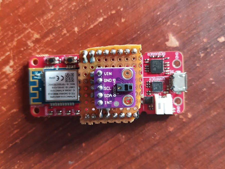
Brief: This page explains how to measure hearbeat realtime, and showing the result on Firebase platform. This project using minimal resource & effort to applied, and easier path to built. As always, this project is beginner friendly and easier to catch.
1. Hardware & Software PreparationWe need to prepare those mentioned hardware above, those are: AVR IoT WG, Hearbeat sensor MAX30100, and micro usb cable. We need aware that sensor MAX30100 is different from MAX30102, I have both of sensors and MAX30102 was not working well. Actually, it would be working well if we can attach 2 PWM pins for the IR and Red Led, which mean we need more coding and effort for these features. For instance, we can directly use heart rate sensor module from Mikro-e (Link) which has compatible Pins with our Dev board AVR IoT WG. Since it was not available in local store, we need to find the another version of heart rate board sensor, and soldered them on a PCB.Besides the hardware, we need also to collect the supporting software, that is AVR Studio. But now it is renamed to Microchip Studio. I used both of them, and found compiling error in Microchip Studio, which not happened in AVR Studio, so I compiled this Projects programs on AVR Studio, We can download the software on repository that provided by microchip. The last, do not forget to sign up for free subscription at google cloud, activate the payment method for your project.
2. Build The ProjectConnect the AVR IoT WG using micro usb cable to PC, wait till pop-up appear. There are example how to measure the built up sensor (light and Temperature) in CLICKME.htm. On the page also mentioned how to connect our device to FIREBASE console and Google cloud. But first, we need to configure the board to be able to measure the newly attached sensor. To do this, we can do several way: Read the datasheet and implement the application note, Or using Atmel start library package. I've tried both of them, and choose to use atmel start, since founded errors during implementation using maxim library which will explained later.Go to atmel start page and browse example for AVR IoT. We need to put additional software component package, shown in fig below:
Don't forget to settings wifi ssid and password. we also can set the settings in project file in case we forget to set it up on device tree diagram. Then generate the code, then try to compile it. Then download the binary file to MCU flash. We can check if the device connected to our SSID by looking at the led indicators, or checking the CLICKME file in the device storage. If the device successfully connected, we can check the page, then it will look like the figure below:
The generated file give us additional file library for sensor MAX30100 that we can use it. As I mentioned earlier, we can change the settings in file library. Wifi SSID and password, Google cloud IoT Settings also stored in folder config.
Make sure the Sensornode Settings is exacly has the same setting as in google cloud platform. This settings will impact on sensornode mqtt publishing data. Then we need to call the function in click_example.h, the function is HeartRate_count(void), we need to do little modification in this function, We need only basic skill in C programming, shown in code below.
while (1) {
    TMR0MS_ISR();
    checkSample();
    if (checkTimeDiff(tsLastReport) > REPORTING_PERIOD_MS)
    {
	bpmRate      = getBPMRate();
	tsLastReport = timer_ms;
	cnt++;
	if (cnt>3){
	    break;
	}
    }
}
    heartrt = (int) bpmRate;
    return heartrt;
This function has no header, so we need to create the header in click_example.h. Then we call this function in main file
#include "click_example.h"

void sendToCloud(void)
{
    static char json[70];

    // This part runs every CFG_SEND_INTERVAL seconds
    int rawTemperature = SENSORS_getTempValue();
    int light          = SENSORS_getLightValue();
    int bpm	        = HeartRate_count(); // call the heartrate function
    // put measurement sensor to json buffer
    int len = sprintf(json, "{\"Light\":%d,\"Temp\":\"%d.%02d\",\"HeartRate\":%d}", light, rawTemperature / 100, abs(rawTemperature) % 100,bpm);
    if (len > 0) {
	CLOUD_publishData((uint8_t *)json, len);
	LED_flashYellow();
    }
}
In order to show the data in firebase platform, we need to configure our google cloud by following this step. In that tutorial, it is automatically generate the device registry in our cloud project. The result will be look like in this figures below:
Make sure that billing is applied to the project, If the firebase installation is successful, Firebase will ask your permission to use the google cloud account. We can monitoring published data from the cloud:
We can also watch the status data from firebase console. And finally, we can watch our heart rate data online by using firebase hosting:
We may facing some problem when developing this project, for example:- If we implement MAXIM application note for MAX30100, it will report an exceed memory limit on AVR IoT WG. Of course there is no other way except reducing the code from the library. This may happened for Algorithm file that needs large memory spaces. Alternatively if we want to implement this method, we can add another MCU (I've tried STM32F103CBT6) as slave to report the measured heart rate. With this algorithm, the measurement is more accurate and reliable rather than ATMEL Start has.
Error unrecognized message format, if we trace them in google cloud, it will give the same result. In my case, the reason is firebase app has no permission from user.


_1x_bGT19vVAby.png?auto=compress%2Cformat&w=40&h=40&fit=fillmax&bg=fff&dpr=2)

Comments
Please log in or sign up to comment.