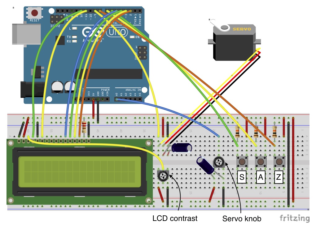
The idea is to realize an instrument panel to control a servo and display the angle and sweep mode on a LCD screen. Although compact and cheap boards dedicated to servo testing do exist, I wanted to realize a device to control and display the flap deflection of a wing model in a little, didactic wind tunnel and I wanted to do it, as far as possible, with the items provided with the Arduino Starter Kit.
How it worksUsually, servo testers give the possibility to control the servo angle by rotating a knob, put the servo in the neutral position, and sweep automatically between the minimum and maximum angle positions. Since my objective is to provide a user interface for wing angle of attack variation or control surface deflection, I do not need to put the servo in the neutral position (i.e. 90° if the servo rotates between 0° and 180°), but I need a switch to set a reference zero angle. In fact, the servo may be at any position while the wing (or control surface) angle relative to the wind is null. Also, I am interested to measure the deflection of the control surface relative to the reference zero. Finally, I want the servo to automatically sweep between two given angles around the reference zero at a certain angular velocity, which I want to control, although I am not interested in measuring it (I just want it to rotate faster or slower).
In my case, I used a little servo with JR connector, I assumed that the flap angle is equal to the servo angle (this is a rough estimate), and the auto-sweep function has been set between -30° and +60° (positive values, means increase in lift force: flap rotates down, the aerodynamic force increases upwards.
The panel operates in two modes: manual control and auto sweep. The user interface provides three buttons, a knob, and a LCD screen. The display shows the servo angle in manual control mode and the limit angles (set in the Arduino code and not editable from the panel) in auto-sweep mode. The switch buttons serve as zeroing the reference angle, commuting between the manual control and auto-sweep mode, and changing the sign of the angle reported on the LCD display. In fact, since the servo rotation may be opposite to the desired convention, the last switch button gives the possibility to change the sign on the screen, but does not invert the rotation of the servo, which is linked to the rotation of the knob. In manual control mode, the servo knob controls the servo angle, which is shown on the LCD screen. Initially, the display shows the servo absolute angle, after the zeroing it shows the servo angle relative to that zero. In the auto-sweep mode, the servo knob controls the rotation rate by adjusting the delay between consecutive rotations (between 15 and 100 ms).
Final noteI have managed to use items from the Arduino Starter Kit, except for the bigger breadboard. The panel shown in the final picture has a slightly different arrangement from the breadboard scheme for assembly reasons. Consider that you may need an external power source to control the servo, according to the voltage and power consumption of your device. If the servo vibrates, check your connections, then try to add an external power source. You may need to rearrange some of the items on your breadboard.
Although incorrect, I have kept the original names for the code filename, variables, and display statements. Angle of attack, alpha, AOA are synonymous, defined as the angle between a reference line and the wind direction in the longitudinal plane. In my application, I have changed the deflection angle of a control surface, which also changes the angle of attack, by altering the local wind direction due to the pressure difference between the upper and lower wing surfaces. By AOA on the display I mean servo angular position, which is related to the control surface deflection by the linkage system. The variation of angle of attack and lift force due the control surface deflection is related to the control surface effectiveness.


_ztBMuBhMHo.jpg?auto=compress%2Cformat&w=48&h=48&fit=fill&bg=ffffff)


_3u05Tpwasz.png?auto=compress%2Cformat&w=40&h=40&fit=fillmax&bg=fff&dpr=2)
Comments
Please log in or sign up to comment.